
A contactor can have the correct current rating and mounting dimensions and still fail after replacement because its coil specification is different. A1 and A2 identify the contactor coil terminals; the manufacturer’s markings and documentation determine their electrical requirements.
Understanding A1 and A2 starts with separating the control circuit from the main power circuit. Once that distinction is clear, contactor wiring, polarity, voltage selection, and troubleshooting become easier to understand.
What Are A1 and A2 on a Contactor?
A1 and A2 are the two electrical terminals connected to a contactor’s electromagnetic coil. When the correct control voltage is applied across them, current flows through the coil and creates a magnetic field. The magnetic force moves the armature, changing the state of the contactor’s power and auxiliary contacts.
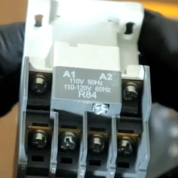
Source: YouTube @SYNECTUM
The A1 and A2 markings identify the coil terminals; they do not indicate positive, negative, line, or neutral. The required voltage, AC/DC type, frequency, and polarity depend on the coil design and manufacturer’s specifications.
The physical position of A1 and A2 varies by contactor design. They may be located above, below, or beside the main power terminals.
Look for A1/A2 markings on contactor housings and confirm their location against the manufacturer’s drawing. Some devices provide duplicate access points to the same electrical terminal. Others, particularly sealed contactors, use leads or connector pins instead of exposed screws.
When reading a contactor wiring diagram, follow the printed A1/A2 markings rather than assuming that the smaller terminals have a standard physical position.
Contactor Terminal Markings: A1/A2, L1/T1, and Auxiliary Contacts
When several terminal groups appear together, identify each one by function rather than assuming they serve the same purpose.
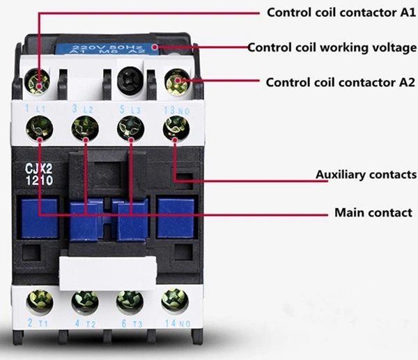
| Terminal Marking | Typical Function | Circuit | Typical Role |
|---|---|---|---|
| A1 / A2 | Contactor coil | Control | Energizes the contactor |
| 1/L1, 3/L2, 5/L3 | Incoming line | Main power | Supply connection |
| 2/T1, 4/T2, 6/T3 | Outgoing load | Main power | Switched output |
| 13–14 | Normally open auxiliary | Control/signaling | Closes when the contactor operates |
| 21–22 | Normally closed auxiliary | Control/signaling | Opens when the contactor operates |
| 95–96 | Overload relay contact | Protection/control | Opens during an overload trip |
The key distinction is that A1/A2 belong to the control circuit, while L1/T1, L2/T2, and L3/T3 typically belong to the main power circuit.
The term “normally” means the device’s unoperated condition. Auxiliary contacts handle signaling, interlocking, or holding circuits within their ratings. They aren’t substitute motor terminals.
Technical Note:
IEC 60947-4-1 specifies requirements and scope for contactors and motor-starters. Its equipment voltage limits should not be confused with the contactor coil rating. Always use the specific product marking or datasheet to identify the coil voltage.
How Do A1 and A2 Work in a Contactor?
When the specified voltage is applied between A1 and A2:
- Current flows through the coil.
- The coil generates magnetic flux.
- The magnetic field attracts the armature.
- The contact mechanism changes state.
- Normally open contacts close and normally closed contacts open, according to the contactor design.

Contactor Working Principle
Source: https://www.electricaltechnology.org/2020/06/electrical-contactor.html
For a conventional non-latching contactor, removing coil power normally allows a spring to return the mechanism to its unoperated position.
Latching contactors operate differently. They may use a pulse or another specified release mechanism, so you should not assume that removing power from the coil will always open the contacts.
For conventional AC coils, pull-in and holding behavior can differ because the magnetic circuit changes as the armature seats. If insufficient voltage, a mechanical obstruction, or another fault prevents the armature from fully closing, the coil may operate abnormally and overheat.
Does A1 and A2 Polarity Matter?
Polarity depends on the contactor coil design. AC coils generally do not have fixed polarity, while some DC coils require a specific A1/A2 connection because of an internal diode or electronic circuit.
AC Contactors
A conventional AC coil generally does not have fixed polarity because the supply alternates. A1 and A2 can therefore normally be connected in either direction, provided the coil receives its specified voltage and frequency.
However, A2 is not automatically neutral. Depending on the control circuit, it may be connected to neutral, another line conductor, or another designated control return.
Neither A1 nor A2 is a protective-earth terminal unless the manufacturer specifically defines it otherwise.
DC Contactors
For a DC contactor, coil construction and any integrated suppression or control electronics determine whether polarity must be observed.
A conventional non-polarized DC winding may accept either direction. A suppression diode, permanent-magnet mechanism, or electronic economizer can change that.
If the manufacturer marks A1 as positive and A2 as negative, follow those assignments. Reversing the polarity can prevent operation or damage the suppression or electronic circuitry.
Use only approved suppression. A basic flyback diode slows current decay. A different clamp arrangement can accelerate release. That timing is important when disconnecting a load.
👉 Further Reading: What’s the Difference Between AC and DC Contactors? A Detailed Guide
What Voltage Goes to A1 and A2?
The voltage applied across A1 and A2 must match the contactor coil’s specified rating.
Common contactor coil ratings include 12 VDC, 24 VDC, 24 VAC, 48 VDC, 120 VAC, and 240 VAC. These ratings are not interchangeable, even when the voltage values appear similar, because AC and DC coils have different electrical requirements.
Before connecting A1 and A2, check:
- Find the coil voltage printed on the contactor or datasheet.
- Confirm whether it is AC or DC. For AC coils, verify the required frequency.
- Check whether the coil has polarity markings.
- Measure the actual control voltage supplied to A1/A2.
- Compare the measured value with the manufacturer’s pickup and holding limits.
Do not determine coil voltage from the motor voltage, main contact current, number of poles, or contactor physical size.
When replacing a contactor, verify the complete part number and coil specification rather than relying on the housing or current rating.
For the sake of a calculation example, a plain 24 V DC, 6 W coil draws 0.25 A at its rated steady condition (I=P/V). This calculation doesn’t establish an electronic coil’s startup demand.
How to Select a Contactor
A1/A2 coil specifications are only one part of contactor selection.
For EV, battery storage, solar, charging, and industrial DC systems, verify:
- System voltage
- Continuous current
- Switching current
- Breaking capability
- Load type
- Switching frequency
- Coil voltage
- AC/DC coil type
- Coil polarity
- Auxiliary contacts
- Precharge requirements
- Environmental conditions
- Required certifications
Before replacing a contactor, compare the complete specification rather than relying on physical size or current rating. Two contactors with similar housings can have completely different coil voltages or coil configurations.
ELEHUB provides DC and high-voltage DC contactors for EV, energy storage, solar, charging, and industrial applications. For model selection, provide the operating voltage, current, load type, control voltage, switching frequency, and application schematic.
How to Wire A1 and A2 Contactor
There is no universal A1/A2 wiring arrangement. The connection depends on the control circuit, while the coil specification determines the required voltage, frequency, and polarity.
Before changing contactor wiring, isolate and lock out any relevant sources before making any changes to the connections, take into consideration any energy that has been stored, and make sure there is no voltage present. OSHA requires a qualified person to test exposed circuit elements before treating them as deenergized.
Typical Three-Wire Starter
For a typical three-wire starter, the A1 and A2 connections on a contactor form this control path:
- The control supply passes through the normally closed Stop button.
- The circuit passes through the normally closed overload contact.
- Pressing the normally open Start button energizes the contactor coil.
- The coil is energized through A1 and A2.
- An auxiliary normally open contact provides the holding path after Start is released.
- Opening Stop or tripping the overload removes coil power and releases the contactor.
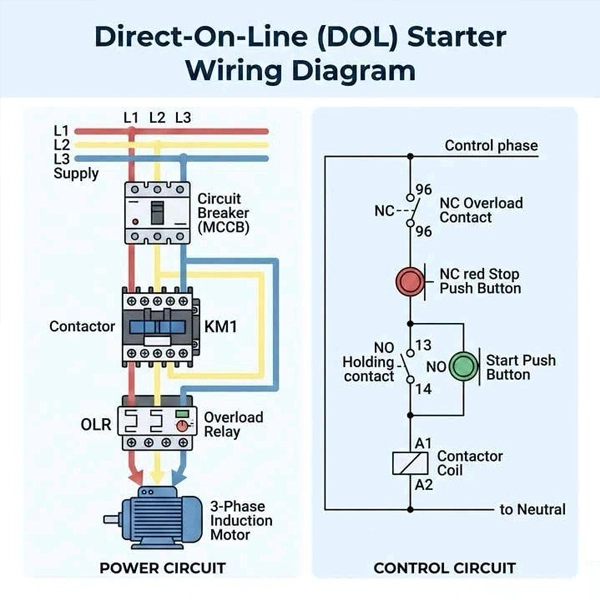
Three-Wire Starter Wiring Diagram
This describes operating logic and not a complete safety circuit. Conductor sizing, terminal torque, overcurrent protection, emergency-stop functions, and interlocks must be determined by the equipment design and applicable requirements.
The shared control arrangement looks like this. K1 identifies the same contactor throughout:
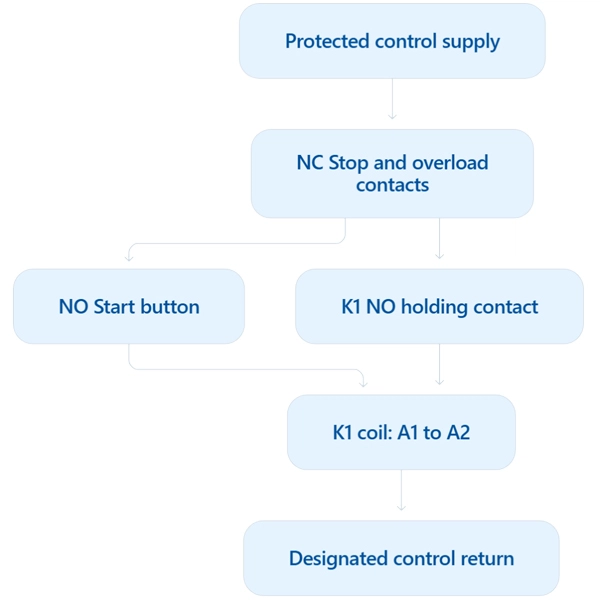
Logic Flow Diagram of Self-Locking Motor Starter
In this A1 A2 contactor wiring arrangement, a power interruption drops out K1. Restoring power alone should not restart it when Start is released, and no alternative command path exists.
Single-Phase Contactor Wiring Diagram A1 A2
For single-phase equipment, the contactor A1 and A2 connections remain separate from the load-pole arrangement. The drawing must identify which supply conductors need switching.
In a 220 V AC control circuit supplied line-to-neutral, the switched line may feed A1 and the neutral may connect to A2, provided the contactor has a compatible 220 V AC coil.
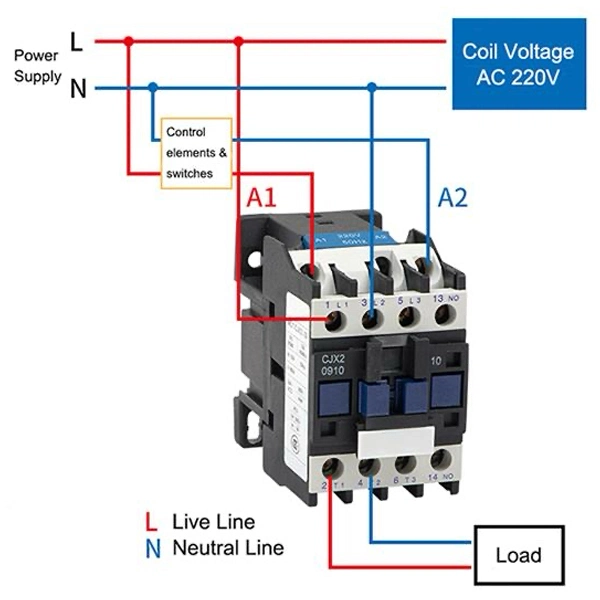
Single-Phase Contactor Wiring Diagram
3 Phase Contactor Wiring Diagram A1 A2
For a 3-phase motor, route the phase conductors through the suitable main poles and coordinate overload and short-circuit protection. The coil may use a separately derived control supply.
A contactor wiring diagram should identify the coil circuit and main power circuit separately. Do not infer the coil supply from the motor’s phase count. The control circuit may use a separate supply.
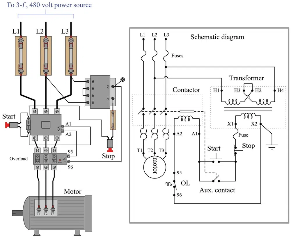
3 Phase Contactor Wiring Diagram
PLC and Battery-Powered Controls
Contactor A1 A2 wiring changes with output architecture. For DC controls, a sourcing output switches the positive side. A sinking output switches the return. Confirm current capacity, leakage, and inductive-load compatibility before connecting a coil directly to a PLC.
For example, with a compatible polarized 24 V DC coil and a low-side driver, A1 connects to the protected positive supply. A2 connects through the driver to 0 V. When many coils are able to activate simultaneously, it is important to check the shared-output current limits.
For the contactor connection A1 A2 interface, use an appropriately rated interposing relay or driver when the controller cannot supply the required current. In order to acquire a closing command, you should not circumvent any existing interlocks.
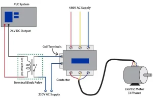
PLC and Relay Controlled 3-Phase Motor Wiring Diagram
How to Test A1 and A2 on a Contactor
During testing, separate the condition of the coil winding from the control voltage actually delivered to it.
Resistance Check
With the circuit properly isolated and de-energized:
- Verify that the circuit is safe to work on.
- Disconnect the coil from external parallel paths as required by the manufacturer.
- Measure resistance directly between A1 and A2.
- Compare the result with the manufacturer’s specification.
Source: YouTube @SYNECTUM
An open reading can indicate a broken winding. An unusually low reading requires comparison with the specified coil. The reason might be that some healthy coils have low resistance. There’s no universal acceptable ohm value, and continuity alone cannot rule out shorted turns.
Integrated electronics can invalidate a basic winding-resistance check. In its place, you should adhere to their diagnostic procedure. Don’t apply an insulation tester across electronic coil inputs without first receiving authorization or approval from the manufacturer.
Control-Voltage Check
When energized diagnosis is necessary, a qualified person should measure directly across A1 and A2 during the command using appropriately rated equipment and protective procedures. Measuring each terminal against ground can be misleading, such as with switched returns.
Compare pickup behavior with the specified limits. PWM-controlled coils may demand waveform or current analysis rather than a single averaged voltage reading.
A1/A2 Contactor Troubleshooting
A practical troubleshooting approach is to connect each observed symptom with the most likely source and then verify the relevant part of the circuit.
| Observation | Possible Causes | First Check |
|---|---|---|
| No voltage during a valid close command | Blown control fuse, open interlock, broken conductor, or missing return path | Measure voltage directly across A1 and A2 |
| Rated voltage present, but no movement | Open coil winding, incorrect polarity, failed coil electronics, or seized mechanism | Verify coil type and polarity, then inspect the mechanism |
| Repeated chatter | Supply voltage sag, loose connection, unstable control signal, or incomplete armature seating | Measure A1–A2 voltage while the contactor operates |
| Excessive heating | Incorrect voltage or frequency, unsuitable duty cycle, poor ventilation, or winding damage | Compare the actual supply with the coil’s rated specifications |
| Contacts remain closed after release | Unwanted holding current, mechanical sticking, or welded contacts | Confirm coil voltage is removed, then inspect the contacts |
For a contactor coil wiring fault, capture conditions during the failure. For example, a supply falling from 24 V to 18 V represents a 25% voltage drop. Whether that voltage is sufficient for pickup or holding depends on the contactor’s specified operating range.
A clicking mechanism doesn’t prove that the power contacts conduct properly. If the coil operates but the load stays off, continue diagnosis through the power circuit.
A1/A2 in Modern DC Power Systems
In battery systems, A1 and A2 are part of the coordinated control strategy used to operate contactors. TI shows an arrangement with two main contactors and one precharge contactor, which charges the DC-link capacitor before the main connection is made.
Coil economizers reduce the current needed to hold after pickup. TI example architecture also talks about external PWM control up to 25 kHz, which is not a universal setting. Internal economizers require the drive as specified by the manufacturer.
Additionally, the A1 and A2 contactor interfaces support fault monitoring. However, a command signal is unable to independently check contact position. The designers of the system are responsible for selecting the proper feedback and protective devices.
Some HVDC contactors also have load-side current-direction requirements. Check the power-pole markings separately from the coil connections. A valid control connection cannot compensate for an arrangement that is not appropriate for the load-side circuit.
Conclusion
A1 and A2 identify the two terminals of a contactor coil. The correct coil voltage, frequency, AC/DC type, polarity requirements, and operating limits must be verified from the manufacturer’s specifications.
When wiring or troubleshooting a contactor, separate the control circuit from the main power circuit. Measure the control voltage directly across A1 and A2, and if the coil operates but the load remains off, continue diagnosis through the main power circuit.
FAQs
How should A1 and A2 be connected on a contactor?
A1 and A2 connect to the contactor’s control circuit and must receive the specified coil voltage. The exact connection depends on the coil type, control circuit, and manufacturer’s wiring diagram.
Is A1 positive or negative on a contactor?
A1 is not inherently positive or negative. Conventional AC coils generally have no fixed polarity, while some DC coils with diodes or electronic components require a specified A1/A2 polarity.
Is A2 always neutral?
No. A2 is a coil terminal, not a dedicated neutral terminal. Depending on the control circuit, it may connect to neutral, a DC return, another line conductor, or another designated control return.
Can A1 and A2 be reversed?
It depends on the coil design. Many conventional AC coils can operate either way, but polarized DC coils and assemblies containing diodes or electronics may require the specified polarity.
What happens if the wrong voltage is applied to A1 and A2?
An incorrect coil voltage can prevent pickup, cause chatter or overheating, or damage the coil or its electronic components. Always match the applied voltage and frequency to the specified coil rating.
Why does a contactor click but the motor does not start?
A click indicates that the mechanism may have operated, but it does not prove that the main contacts are conducting correctly. Check the main power circuit, contacts, overload protection, wiring, and load.


