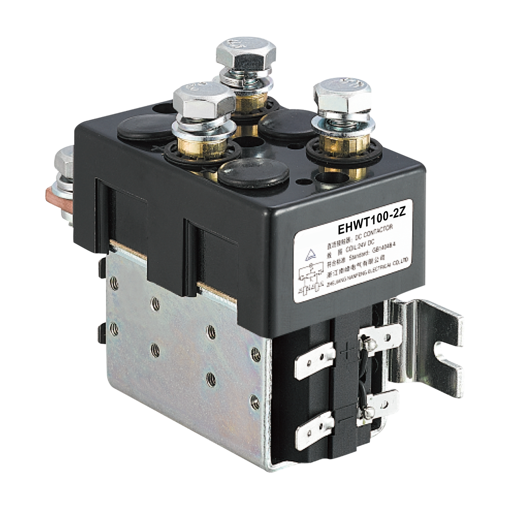
The contactor coil is a key component in circuits that control high-power devices, such as heating elements, lighting systems, and motors. The coil is a fundamental component of a contactor that generates a magnetic field, enabling the device to safely and efficiently switch high currents.
In both industrial and residential applications, many high-power devices are controlled using small control switches. This controlled operation is made possible by the contactor coil, which allows low-power control signals to manage high-power electrical loads.
In this tutorial, we explore how contactor coils work, their voltage and current characteristics, key differences between AC and DC coils, testing methods, and common troubleshooting practices used in real-world electrical systems.

Key Takeaways
- Contactor coils allow low-power control of high-current loads
- AC and DC coils are not interchangeable
- Incorrect coil voltage on contactor causes overheating, chatter, or failure
- Proper testing and maintenance extend coil life to 5–10 years
Let’s get started.
How Does a Contactor Coil Work?
A contactor coil is an electrically operated component whose main function is to control a high-power circuit using a low-power control signal. Its operation involves several steps.

Voltage Application to the Coil
When voltage is applied to the coil, current flows through the copper windings. This current generates a magnetic field, following the principles of electromagnetism. The strength of the magnetic field depends on the applied voltage and the number of turns in the coil. The generated magnetic field attracts the armature.
Armature Movement
In a contactor, a movable metallic component called the armature is present. The magnetic field produced by the energized coil pulls the armature toward the coil. In some sources, the armature is also called the plunger or moving magnetic core, especially in DC contactors.
The armature is mechanically connected to the main contacts of the contactor. When the armature moves, it causes the contacts to close and completes the circuit.
Closing the Contacts
Once the armature moves into position, the main contacts close, allowing current to flow to the load. Devices connected through the contactor, such as motors, heaters, or lighting systems, receive power.
Although the coil itself draws only a small current, it safely controls and switches a much higher current. For this reason, a contactor coil acts as a remote switch that uses magnetic force to control heavy-duty electrical loads.
Coil De-energizing
When the voltage supply to the coil is disconnected, current flow stops and the magnetic field collapses. As a result, the armature returns to its original position by spring action.
When the contacts open, the main circuit is broken, and current flow to the connected device stops.
AC vs DC Contactor Coil Voltage
|
Feature
|
AC Contactor Coil
|
DC Contactor Coil
|
|
Supply Type
|
Functions on Alternating Current (AC)
|
Operates on Direct Current (DC)
|
|
Current Feature
|
Current changes direction periodically (50/60 Hz)
|
Current flows in one direction only
|
|
Magnetic Field
|
The magnetic field increases and decreases each cycle
|
The magnetic field is steady and constant
|
|
Core Design
|
Complicated comes with a shading ring to prevent chatter
|
Simpler core, no shading ring used
|
|
Noise Level
|
Humming sound produce
|
Quiet operation
|
|
Inrush Current
|
High inrush current at energizing
|
Low and stable current
|
|
Arc / Chatter Control
|
Special design due to zero-crossing
|
Naturally stable, less chatter
|
|
Coil Impedance
|
Depends on inductance + frequency
|
Mostly depends on resistance
|
|
Coil Marking
|
230V AC, 50/60 Hz
|
24V DC
|
|
Protection Components
|
None external
|
Uses a flyback diode or suppressor
|
|
If Wrong Supply Applied
|
DC on AC coil, overheating
|
AC on DC coil, chatter/failure
|
|
Applications
|
Industrial machines, HVAC motor starters, lighting control
|
Battery systems, solar, EVs, PLC control
|
Further Reading:
What is an AC Contactor & How to Tell if It’s Failing?
What is a DC Contactor: Everything You Need to Know
What’s the Difference Between AC and DC Contactors? A Detailed Guide
Contactor Coil Specifications
Voltage Rating
Voltage rating indicates the voltage level at which the coil operates correctly. This voltage produces the magnetic field required to pull the armature and close the contactor contacts.
If the applied voltage is higher than the rated value, the coil can overheat, leading to insulation damage and eventual coil failure. If the applied voltage is lower than the rated value, the magnetic field becomes too weak to pull the armature properly, which can cause contactor chattering and incomplete contact closure.
How to Check Contactor Coil Voltage?
To check contactor coil voltage:
- Inspect the label or nameplate on the contactor or coil module. Manufacturers usually print the rated coil voltage on contactor, such as 24VDC, 120VAC, or 230VAC.
- Check the technical datasheet using the model number
- If the marking is unclear, use a multimeter to measure the voltage across the coil terminals (typically A1 and A2) while the control circuit is energized. Set the meter to AC or DC mode depending on the system type.
- Always verify both the contactor coil voltage rating and whether the coil is designed for AC or DC operation before energizing the contactor.
Common Contactor Coil Voltage Ratings:
- AC: 110V, 120V, 220V, 230V, 400V
- DC: 12V, 24V, 48V, 60V, 110V
Coil Current
Contactor coil current refers to the amount of current drawn by the coil during energization. This current is relatively small compared to the current flowing through the main contacts.
Push buttons, control circuits, relays, or PLC outputs supply this current. If the coil draws excessive current, it can overload control devices and negatively affect associated components.
Power Consumption
Power used during coil energization is called power consumption. It is measured in watts and depends on the applied voltage and current.
If high power is used by the coil, it can cause overheating, which may damage the coil structure and affect connected devices. Accurate coil power ratings allow continuous energization in HVAC systems and automation panels without overheating.
Coil Resistance
The resistance of the coil defines the current flow through the coil at a given voltage. Resistance is measured in ohms and is mainly considered for DC contactor coils.
If the resistance value is low, high current flows and produces a strong magnetic field, but it also generates excessive heat. High resistance limits current flow, producing less heat but a weaker magnetic force. Therefore, the resistance value must balance magnetic strength and safe operation.
Contactor Coil Resistance Test
A contactor coil resistance test is a simple way to check whether a contactor coil is intact, shorted, or open using a multimeter:
- Turn OFF power to the contactor completely for safety
- Disconnect coil terminals (A1 and A2) from the control circuit
- Set a multimeter to resistance (Ω) mode
- Place probes on A1 and A2 terminals
- Read the resistance value on the display
|
Test Result
|
Meaning
|
|
Normal resistance value (within datasheet range)
|
Coil is healthy
|
|
OL / Infinite resistance
|
Coil is open (broken winding)
|
|
Very low or near 0 Ω
|
Coil is shorted (damaged insulation)
|
|
Unstable readings
|
Possible internal coil damage or poor connections
|
Duty Cycle
The duty cycle defines how long a coil remains energized within a given time period.
A 50 percent duty cycle means the coil stays energized for half of the time and remains de-energized for the other half, allowing it to cool.
If the duty cycle is not considered, excessive heat can build up and damage the coil.
How to Select the Right Contactor Coil
Different factors must be considered for selecting the correct coil:
System Voltage & Type
The first and most important parameter is matching the coil voltage and type with the control system. Always check whether the control circuit operates on AC or DC voltage.
Use a coil with the same voltage rating, such as 24V DC or 230V AC. Using an incorrect voltage rating results in improper coil operation and can cause coil damage or failure.
Control Circuit Capacity
The control circuit must be capable of supplying the required coil current. Ensure that PLC outputs, push buttons, timers, and relays are rated to handle the coil’s holding current and inrush current.
If the control circuit is undersized, it can cause nuisance tripping of protection devices or unreliable contactor operation.
Duty Cycle
The duty cycle indicates how long the coil can remain energized continuously. In applications where the contactor must stay energized for long periods, a 100 percent duty cycle coil is required.
A low-duty-cycle coil is suitable only for short-duration or intermittent operations.
Environmental Conditions
Coil operation is also affected by environmental conditions. High temperatures can degrade insulation, while moisture can damage insulation and cause corrosion. Vibration can affect electrical connections and interfere with mechanical movement.
Contactor Coil Wiring & Installation
Follow these steps for the coil wiring and installation process.
1. Turn Off Power
First, turn off or disconnect the main power supply using a circuit breaker or isolation switch. Ensure with a multimeter that no current is flowing. This prevents electric shock and protects devices from accidental short circuits.
2. Connect Coil Terminals
On the contactor, locate coil terminals such as A1 and A2. Connect these terminals to the control voltage supply according to the manufacturer’s specifications.
Use proper wire size and insulation for the control circuit. Check that the supplied voltage matches the coil’s rated voltage.
Accurate terminal connections help the coil receive a stable supply for reliable operation.
3. Proper Polarity (For DC Coils)
Polarity is important when wiring DC contactor coils. Connect the positive and negative terminals correctly.
Reversed polarity can affect coil energization or damage components such as suppression diodes. For AC coils, polarity is not required
4. Strong Connections
Make wiring connections tightly, since loose connections cause overheating, arcing, and voltage losses. Loose connections can also burn terminals and coils.
Use accurate tools to tighten screws according to the required torque value.
5. Test Before Function
After completing the wiring process, perform functional testing. In this test, energize the coil with the control voltage. If a clicking sound is produced, it means the armature is moving properly. Perform a visual inspection to check that the contactor contacts open and close accurately.
How to Test a Contactor Coil
Test the contactor coil for troubleshooting and maintenance purposes. This helps determine whether the coil is working properly or requires replacement. The following steps are involved in testing the contactor coil.
1. Visual Inspection
Check for dust, moisture, and corrosion, especially in humid or dusty environments.
2. Resistance Calculation
With the help of a multimeter, check the resistance by selecting the ohm mode. In this test, disconnect the coil power supply. Then place the meter probes on coil terminals A1 and A2.
Compare the measured resistance with the manufacturer-defined value.
If the reading shows infinite resistance, it indicates an open coil, while low resistance indicates a shorted coil. In these conditions, the coil must be replaced.
3. Apply Control Voltage
In this step, use the rated control voltage for the coil. Energize the coil and listen for a clicking sound, which indicates that the armature has pulled in and the contacts have closed.
If no sound is heard, it may indicate insufficient voltage or a faulty coil.
4. Magnetic Pull Inspection
Check the armature movement during coil energization. The armature should move smoothly toward the coil without vibration or sticking. When the voltage is removed, the armature should return to its original position.
If the movement is not smooth, it may indicate dust buildup or a weak coil.
Contactor Coil Troubleshooting
Contactor coils may develop faults over time due to environmental conditions, electrical stress, or mechanical wear. Accurate troubleshooting helps identify problems quickly, minimizes downtime, and prevents system damage. Below are some common contactor coil faults and their solutions.
Coil Energizing Problems
If the contactor coil does not energize, it means the contactor is not operating properly. In this case, check that the correct voltage is present at the coil terminals.
Inspect the wiring to identify any faulty, damaged, or loose connections.
Confirm that control devices such as relays, push buttons, and PLC outputs are functioning correctly.
Check the coil resistance to ensure that the coil is not open or damaged.
These issues usually occur due to wiring faults or incorrect control voltage.
Burned Coil
If the coil is burned, it may show signs such as melted insulation, discoloration, or a burning smell. These issues occur due to overheating, which increases current and damages insulation.
Operating the coil at a duty cycle higher than its rated value can also cause overheating and insulation failure. High ambient temperatures and poor ventilation may further damage the coil.
If the coil is burned, replace it immediately to prevent further system damage.
Sticking Contacts
Switching operations can lead to contact sticking over time. Mechanical wear of the armature contributes to this problem. Dust and dirt inside the contactor can also restrict movement.
High arcing causes contacts to fuse, increasing the risk of sticking.
Regular cleaning and inspection help prevent these faults.
Overheating
Overheating affects the working life of the coil and connected components. High ambient temperatures place extra stress on the coil. Low resistance increases current flow, which generates excessive heat.
Continuous operation without proper cooling can exceed thermal limits.
Proper ventilation and using a coil with the correct rating help minimize overheating.
Contactor Coil Calculations
Contactor coil calculations are important for selecting the correct coil, designing the control circuit, and ensuring safe operation. These calculations help prevent overheating, excessive power consumption, and circuit overloading.
Coil Current Calculation
The current flowing through a contactor coil depends on the applied voltage and the coil resistance. It can be calculated using Ohm’s Law:
Coil Current (I) = Voltage (V) / Resistance (R)
This calculation helps determine the current in the control circuit. If the resistance is low, the coil draws higher current and generates more heat.
Accurate current values help select properly rated switches, relays, and PLC outputs. They also protect the control circuit and ensure reliable operation.
Power Consumption Calculation
The power consumed by the coil shows how much energy it uses during operation. The following equation is used to calculate power:
Power Consumption (P) = Voltage (V) × Current (I)
The watt is the unit used to measure power. High power consumption leads to increased heat generation.
Low-power coils are suitable for continuous operation because they minimize energy loss.
Measuring power helps in selecting energy-efficient coils and managing heat dissipation.
Conclusion
A contactor coil is the main component in safe automation and high-power switching. It controls large electrical loads with accuracy and reliability. Understanding its working principle, testing methods, regular maintenance, and proper selection is essential for stable and efficient electrical system operation.
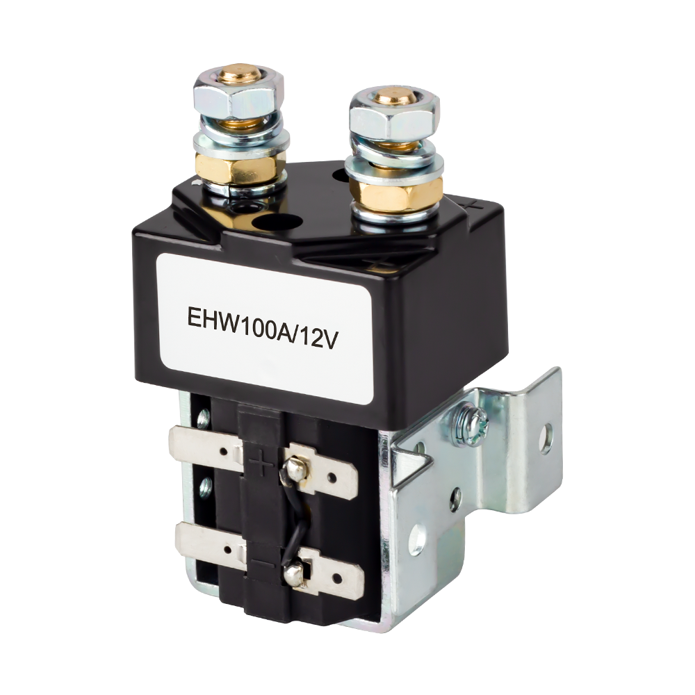
This is especially important in high-voltage DC projects, where durability and safety are important. ELEHUB offers specialized high-voltage DC contactors for industrial and energy system applications, including electric vehicles, battery storage, and power distribution. ELEHUB provides epoxy-sealed high-voltage DC contactors for insulation and vibration resistance, as well as ceramic high-voltage DC contactors designed to withstand extreme temperatures and harsh operating conditions.
Through strong coil design, durable materials, and strict quality standards, ELEHUB ensures accurate switching, long service life, and high safety performance in high-power electrical systems.
FAQs About Contactor Coil Voltage
What is a Contactor Coil?
A contactor coil is an electromagnetic component that uses a low-voltage control signal to switch high-current electrical loads by generating a magnetic field that operates the contactor’s contacts.
What happens if a higher-voltage coil is used than recommended?
Using a higher-voltage coil can cause overheating. A burned coil reduces its working life.
Can AC coils be used in DC circuits?
No, it is not recommended to use AC coils in DC circuits because they do not produce the required magnetic field in DC applications and may damage the circuit.
How often should I maintain my contactor coil?
It is recommended to test and maintain the contactor coil every 6 to 12 months, depending on usage and environmental conditions.
What is the working life of a contactor coil?
With proper maintenance, a contactor coil typically lasts five to ten years, depending on the duty cycle and operating environment.
How do I know if a contactor coil is the proper size for my circuit?
Check the coil current, voltage rating, duty cycle, and structural parameters to ensure compatibility with the control circuit and load requirements.
How to Test a Contactor Coil
- Disconnect power and ensure zero voltage
- Measure coil resistance using a multimeter
- Apply rated control voltage
- Observe armature movement and sound
What causes contactor coil chatter?
Contactor coil chatter happens when contacts rapidly open and close instead of remaining steady. Common causes include:
- Insufficient or fluctuating control voltage
- Using the wrong coil type (e.g., an AC coil in a DC circuit)
- Mechanical issues, such as a worn or sticky armature
- Dust, dirt, or corrosion inside the contactor
- Chatter can increase wear, arcing, and the risk of system damage.
How do you measure contactor coil current?
To measure contactor coil current:
- Power the coil at its rated voltage.
- Use a clamp meter around one coil wire or a multimeter in series with the coil.
- Compare the measured current to the manufacturer’s rated coil current.
- This helps ensure the control circuit can supply sufficient power and detect potential overcurrent conditions.
Can a contactor coil be repaired?
In most cases, contactor coils cannot be repaired due to the tightly wound coils and insulation. If the coil is open, shorted, or burned, it should be replaced with an exact match (voltage, type, and duty rating). Attempting to repair is generally unsafe and not cost-effective.
When a contactor’s coil is energized, how much resistance should be measured between terminal “L1” and terminal “T1”?
When the coil is energized, the contactor’s main contacts (L1 to T1) should be closed, so resistance should be very low, typically near 0 Ω (often below 1 Ω or in milliohms range). A high or infinite reading indicates faulty or non-closed contacts.
When no power is applied to the coil, what happens to the contactor?
When no power is applied to the coil, the contactor returns to its normal de-energized state. Internal springs force the moving contacts to open, breaking the circuit between L1 and T1 (and other poles), stopping current flow and isolating the load.
What contactor mechanical life ratings and coil voltage tolerance indicate high reliability for frequent switching applications?
For frequent switching applications, a highly reliable contactor is typically characterized by a mechanical life rating of at least 10 million operations or higher, with industrial-grade models reaching 20–30 million cycles.
On the electrical side, coil voltage tolerance is also important. High-reliability contactors usually specify a coil operating range of about 80%–110% of rated voltage (some up to 70%–120%), ensuring stable pull-in and hold-in even with supply fluctuations.
Together, a high mechanical life rating plus a wide coil voltage tolerance indicates the contactor can withstand repeated switching and real-world voltage instability without premature failure.
A contactor coil on a residential system operates on what voltage?
In residential systems, contactor coils most commonly operate on 24V AC, especially in HVAC applications like air conditioners, heat pumps, and furnaces. This low-voltage control is used for safety and compatibility with thermostats.
In some residential or light-duty setups, you may also see 120V AC or 240V AC coils, but these are less common in modern HVAC control circuits.
Related Posts:
DC Contactor Working Principle: How Do DC Contactors Work?
Epoxy vs Ceramic DC Contactors: A Deep Technical Comparison
How to Choose the Right DC Contactor for Different Applications