Creepage and clearance are two fundamental measurements used in electrical insulation design. Both define the separation between conductive parts, but they follow different paths and address different insulation risks. Understanding creepage vs clearance is essential for selecting appropriate insulation distances in electrical and electronic equipment.
Creepage distance is the shortest distance along the surface of an insulating material, while clearance distance is the shortest distance through air between conductive parts.
They are important in PCBs, power supplies, battery systems, EV chargers, solar equipment, industrial controls, and high-voltage DC systems. Insufficient spacing can increase the risk of leakage current, tracking, insulation breakdown, or arcing.
This guide explains the difference between creepage and clearance, how they are measured, what determines their required values, and how they are applied in practical designs.

Source: Integrating Power Electronic Equipment into Shipboard Power Systems
🆚 Quick Comparison Table
The main difference is the path used to measure the separation between two conductive parts.
| Feature | Creepage | Clearance |
|---|---|---|
| Definition | Shortest distance along an insulating surface | Shortest distance through air |
| Measurement path | Along the surface | Through air |
| Main concern | Surface leakage and tracking | Air breakdown and arcing |
| Environmental influence | Strongly affected by contamination and moisture | Strongly affected by altitude and transient voltage |
| Material dependent | Yes | Generally less dependent on material |
| Common applications | PCBs, connectors, power supplies | PCBs, terminals, busbars, high-voltage equipment |
Creepage distance and clearance distance are not interchangeable. A design can have adequate clearance but insufficient creepage, or adequate creepage but insufficient clearance.
What Is Creepage Distance?
Creepage distance is the shortest path between two conductive parts measured along the surface of an insulating material.
For example, consider two conductive PCB traces separated by an insulating PCB surface. Creepage distance follows the PCB surface from one conductor to the other rather than passing directly through the air.
Creepage is important because contaminants can accumulate on an insulating surface. Dust, moisture, salt, and other conductive contamination can create a path for leakage current. Under sufficient electrical stress, this can eventually contribute to surface tracking.
What Affects Creepage?
The required creepage distance depends on several factors, including:
- Working voltage
- Pollution degree
- Insulation material
- Comparative Tracking Index (CTI)
- Insulation type
- Applicable safety standard
- Environmental conditions
For this reason, a higher-voltage or more heavily contaminated environment will generally require greater creepage distance.
What Is Clearance Distance?
Clearance is the shortest distance through air between two conductive parts at different electrical potentials.
Unlike creepage, clearance does not follow the surface of the insulating material. It is considered the shortest path through air.
Clearance is primarily intended to prevent electrical breakdown or arcing across the air gap.
For example, if two high-voltage terminals are separated by an air gap, the shortest distance directly between the conductive surfaces is part of the clearance measurement.
What Affects Clearance?
Air is an electrical insulator under normal conditions, but it can break down when the electric field becomes sufficiently strong.
Clearance requirements can be influenced by:
- Working voltage
- Transient overvoltage
- Overvoltage category
- Altitude
- Conductor geometry
- Applicable safety standard
At higher altitudes, air density decreases, which can reduce the dielectric strength of air. Therefore, equipment intended for high-altitude operation may require additional clearance.
Creepage vs Clearance: How Are They Measured?
The basic distinction is simple:
- Creepage: measure along the insulating surface.
- Clearance: measure through air.
For example, if two conductors have a 3 mm direct air gap and an 8 mm path along the insulating surface, the simplified values are:
- Clearance = 3 mm
- Creepage = 8 mm
Actual measurements must follow the applicable safety standard, particularly for complex geometries, barriers, grooves, or other insulating features.
What Determines Creepage and Clearance Requirements?
There is no universal spacing value for a given voltage. Consider the applicable standard and the complete insulation system.
1. Working Voltage
Working voltage is a key input for insulation coordination. Higher electrical stress generally requires greater separation.
AC and DC systems must be evaluated using the voltage definitions specified by the applicable standard.
2. Pollution Degree
Pollution degree is particularly important for creepage because contamination can create conductive paths across an insulating surface.
Typical classifications are:
- Pollution Degree 1
- Pollution Degree 2
- Pollution Degree 3
- Pollution Degree 4
The appropriate classification depends on the equipment’s environment and microenvironment.
3. Insulation Material and CTI
Comparative Tracking Index (CTI) characterizes the tracking resistance of an insulating material under specified test conditions.
CTI can affect creepage requirements, but it should not be used alone to determine the final distance.
4. Transient Overvoltage
Switching events, lightning-related disturbances, and other transients can produce voltages above normal operating levels.
These conditions are important when determining the required insulation withstand capability and clearance.
5. Overvoltage Category
Overvoltage categories classify expected transient conditions within an electrical installation. The applicable category can affect insulation-coordination requirements.
6. Altitude
Altitude mainly affects clearance because the dielectric strength of air decreases as atmospheric pressure falls.
7. Insulation Type
Common insulation classifications include:
- Functional insulation
- Basic insulation
- Supplementary insulation
- Reinforced insulation
The applicable product standard determines the requirements for each insulation system.
Creepage and Clearance Standards
The correct standard depends on the type of equipment. IEC 60664-1 is an important insulation-coordination reference, but product-specific standards may impose additional requirements.
IEC 60664-1
IEC 60664-1 is a major reference for insulation coordination in low-voltage systems. The current consolidated version is IEC 60664-1:2020+AMD1:2025.
It covers factors including:
- Clearances
- Creepage distances
- Working voltage
- Pollution degree
- Overvoltage conditions
- Material characteristics
- Altitude
The current version also includes updated provisions related to 1,500 V DC, clearance and creepage determination, and altitude correction.
IPC-2221
IPC-2221 provides general PCB design guidance, including electrical spacing considerations.
It can support PCB layout decisions, but product-specific safety requirements should be checked for the finished equipment.
IEC 62368-1
IEC 62368-1 applies to audio/video and information and communication technology equipment, including many IT and networking products.
It uses a hazard-based approach to electrical safety and includes requirements related to insulation and spacing.
IEC 61010-1
IEC 61010-1 applies to measurement, control, and laboratory equipment. Its insulation requirements depend on factors such as working voltage, equipment type, and environmental conditions.
IEC 60601-1
IEC 60601-1 applies to medical electrical equipment and systems. It includes requirements for protection against electric shock, including creepage, clearance, and insulation.
Product-Specific Standards
Other products may fall under different IEC, UL, or regional standards.
Therefore, designers should identify the applicable product standard before selecting final creepage and clearance values.
Creepage and Clearance in PCB Design
PCB layout is one of the most common areas where creepage and clearance distances become important.
High-voltage PCB designs may contain:
- AC mains traces
- High-voltage DC buses
- Power converter circuits
- Battery connections
- Switching devices
- Isolation barriers
- High-voltage connectors
PCB Creepage
PCB creepage follows the surface of the board.
This means that two traces can have a relatively short direct air distance while having a longer creepage path across the PCB surface.
The PCB material, contamination level, voltage, and applicable standard must be considered when determining the required distance.
PCB Clearance
PCB clearance is the shortest air distance between conductive features.
Designers commonly check the distance between:
- Copper traces
- Pads
- Terminals
- Via structures
- Conductive mounting hardware
Simply increasing the spacing between traces can increase clearance.
Can a PCB Slot Increase Creepage Distance?
Yes. A slot or groove can sometimes be used to increase the creepage path between two conductive areas.
For example, without a slot, the creepage path may run directly across the PCB surface between two conductors. Adding a properly positioned slot can force the surface path to travel around the opening, thereby increasing the total creepage distance.

Methods to Increase Creepage
However, a slot should not automatically be assumed to increase clearance by the same amount. Creepage and clearance must be evaluated separately based on the actual geometry and applicable standard.
Other methods of increasing insulation distance include:
- Increasing conductor spacing
- Adding insulating barriers
- Changing component geometry
- Selecting an appropriate insulating material
- Increasing PCB surface path length
- Using suitable slots or grooves
Creepage and Clearance in High-Voltage DC Systems
Creepage and clearance are particularly important in high-voltage DC applications because electrical insulation must remain reliable under continuous voltage and transient conditions.
Typical applications include:
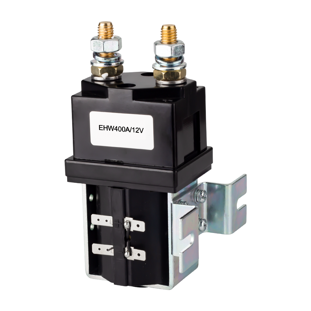
- HV DC contactors
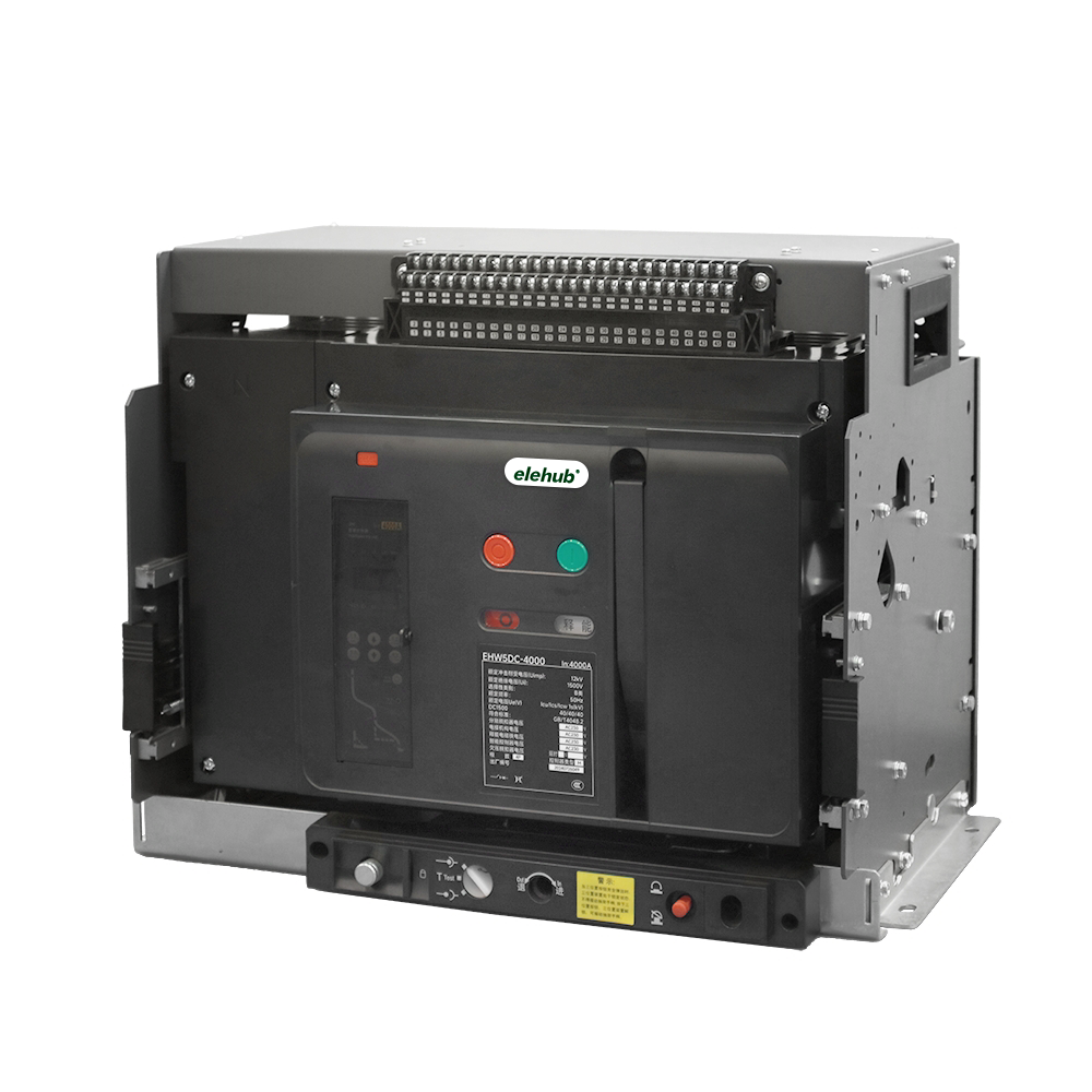
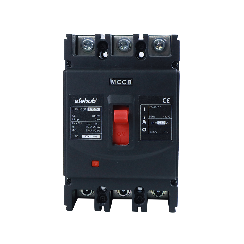
- DC circuit breakers
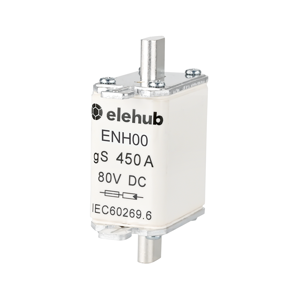
- DC fuses
- Battery energy storage systems
- EV charging equipment
- Solar inverters
- Industrial DC power supplies
- Data-center power systems
High-voltage DC systems also present challenges related to switching and arc suppression. Therefore, creepage and clearance should be considered as part of a broader insulation and protection strategy.
For example, an HV DC contactor must provide appropriate electrical isolation when its contacts are open. The contact spacing, internal insulation, housing design, and other construction features all contribute to the overall isolation performance.

HVDC Contactor Construction
Electrical creepage and clearance distance alone do not determine whether a component is suitable for a particular high-voltage application.
How to Design Creepage and Clearance Distances
A practical design process is:
- Identify the applicable product standard.
- Determine the relevant working voltage and transient conditions.
- Establish the pollution degree and operating environment.
- Define the required insulation type.
- Evaluate the insulating material and CTI where applicable.
- Consider altitude and physical geometry.
- Determine and verify the required creepage and clearance according to the standard.
This approach is more reliable than selecting a spacing value from a generic voltage-to-distance table.
Creepage and Clearance Design Example
Consider a PCB used in an industrial DC power system.
Suppose the system has:
- A 400 VDC working voltage
- An industrial operating environment
- FR-4 PCB material
- Pollution Degree 2
It may be tempting to select a creepage and clearance value based only on the 400 VDC rating.
That approach is incomplete.
The designer should first determine:
- The applicable product safety standard
- The required insulation level
- The relevant working voltage
- Expected transient overvoltages
- Pollution degree
- PCB material and CTI
- Overvoltage category
- Maximum operating altitude
- Actual conductor geometry
Only after these factors are evaluated should the final creepage and clearance requirements be selected.
This is why there is no universal minimum creepage or clearance distance for a given voltage.
Common Creepage and Clearance Design Mistakes
Mistake 1: Measuring Only the Straight-Line Distance
A straight-line measurement through air represents clearance, not necessarily creepage.
Creepage must follow the relevant insulating surface.
Mistake 2: Treating Creepage and Clearance as the Same
They address different electrical insulation risks.
Clearance primarily addresses breakdown through air, while creepage addresses leakage and tracking along an insulating surface.
Mistake 3: Ignoring Pollution Degree
An electrical product used in a clean indoor environment may have different creepage requirements from equipment exposed to industrial contamination, moisture, or outdoor conditions.
Mistake 4: Ignoring Altitude
Altitude can affect the dielectric strength of air and therefore the required clearance.
Mistake 5: Using a Generic Distance Table
A simple voltage-to-distance table cannot always provide the correct answer.
The applicable standard, insulation type, pollution degree, material characteristics, transient conditions, and operating environment must be considered together.
Mistake 6: Assuming Solder Mask Is a Complete Solution
Solder mask can form part of a PCB’s insulation system, but designers should not automatically assume that it eliminates the need to meet the required creepage and clearance distances.
The applicable standard determines how the PCB construction should be evaluated.
Creepage vs Clearance: Quick Reference
| Question | Answer |
|---|---|
| What is creepage? | Shortest path along an insulating surface |
| What is clearance? | Shortest distance through air |
| Main creepage concern? | Surface leakage and tracking |
| Main clearance concern? | Air breakdown and arcing |
| Does pollution affect creepage? | Yes |
| Does altitude affect clearance? | Yes |
| Can CTI affect creepage? | Yes |
| Can a PCB slot increase creepage? | Yes |
| Does a slot automatically increase clearance? | No |
| Are creepage and clearance interchangeable? | No |
| Is there one universal minimum distance? | No |
Conclusion
Creepage and clearance are both essential parts of electrical insulation design, but they measure different things.
Creepage is the shortest path along an insulating surface, while clearance is the shortest path through air. Creepage primarily addresses surface leakage and tracking, whereas clearance helps prevent air breakdown and electrical arcing.
The correct insulation distance cannot be determined from voltage alone. Working voltage, transient conditions, pollution degree, insulation type, material characteristics, altitude, product construction, and the applicable safety standard all need to be considered.
For PCB layouts, power converters, battery systems, EV charging equipment, solar equipment, and high-voltage DC components, evaluating both creepage and clearance early in the design process can help improve electrical safety and insulation reliability.
FAQs
Is creepage always greater than clearance?
No. Neither one is universally greater. Their required values depend on voltage, insulation, environmental conditions, geometry, and the applicable safety standard.
How do I calculate creepage and clearance?
There is no single formula that applies to every product. Determine the applicable safety standard and evaluate working voltage, transient voltage, pollution degree, insulation type, material characteristics, altitude, and other relevant factors.
Can creepage and clearance be different on the same PCB?
Yes. Clearance may be shorter than creepage because clearance is measured through air, while creepage follows the insulating surface between conductive parts.
Does PCB thickness affect creepage distance?
PCB thickness can affect the insulation geometry, but it does not directly determine creepage distance. The actual surface path and applicable safety standards must be considered.
Does PCB coating reduce the required creepage distance?
In some approved insulation systems, coating may affect creepage requirements. However, this cannot be assumed automatically and depends on the coating, construction, certification, and applicable standard.
What happens if creepage distance is too short?
Insufficient creepage can increase surface leakage and tracking risks, particularly under moisture or contamination. Severe tracking can damage insulation and cause electrical failure.
What happens if clearance distance is too short?
Insufficient clearance can allow air breakdown under electrical stress, potentially causing flashover, arcing, insulation failure, or damage to nearby components.
Are creepage and clearance requirements different for AC and DC?
They can be. Standards may define working voltage, transient conditions, and insulation requirements differently for AC and DC systems, so the applicable standard should always be followed.
Do connectors have creepage and clearance requirements?
Yes. High-voltage connectors need adequate creepage and clearance between terminals and other conductive parts. Requirements depend on voltage, insulation material, environment, and applicable standards.