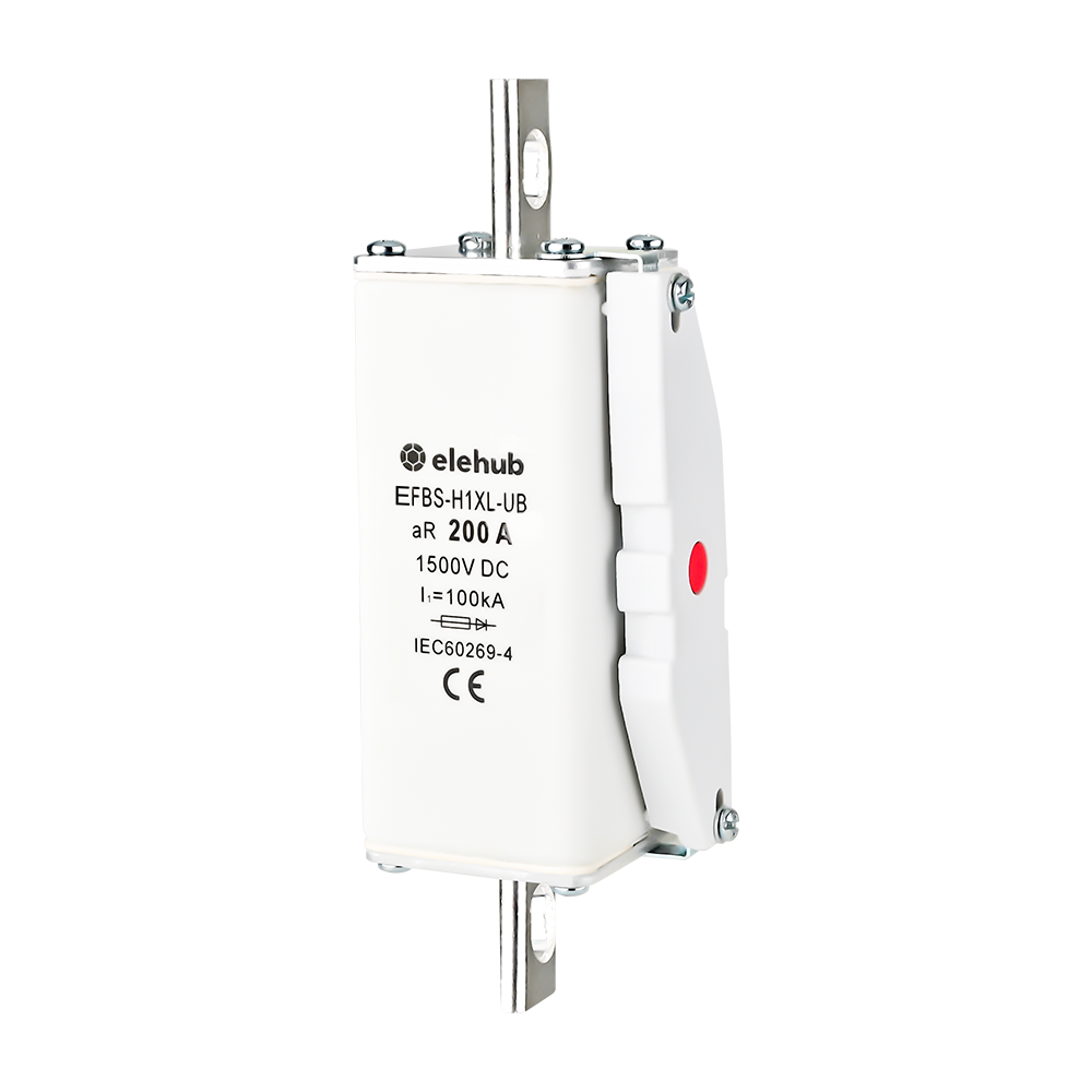
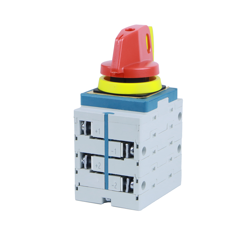
A circuit breaker justifies its existence within an electrical circuit because it has the mission of suppressing excessive current circulation along the conductors caused by short circuits, line-to-ground faults, and other fault conditions. In these events, it prevents the destruction of electrical wiring, damages to the electrical equipment, and minimizes the probability of electrical fires spreading.
In this article, we will go through the circuit breaker types commonly used in an electrical system, regarding their uses in high voltage and medium voltage within the electrical industry, without leaving aside the industrial and domestic applications of low voltage circuit breakers such as ground fault circuit interrupters, or GFCI circuit breakers, and other circuit breakers intended for avoid electrical shocks to electrical system users.
Circuit Breaker definition according to the American National Standards Institute (ANSI)
A technical or scientific definition of what we understand as a circuit breaker can be the one provided by ANSI:
A circuit breaker is a mechanical device capable of making, carrying, and breaking currents under normal circuit conditions and also making, carrying for a specific time and breaking currents under specified abnormal circuit conditions such as those of short circuits.
The National Electrical Code and the regulations on Circuit Breakers
Enforced in all 50 states, NFPA 70, the National Electrical Code (NEC) is the benchmark for safe electrical design, installation, and inspection to protect people and property from electrical hazards.
NEC Article 240 generalizes overcurrent protection and protective devices to avoid damage to the electrical systems. Factors contributing to overcurrent are a demanding environment, overload, general deterioration, and accidental damage to the electrical components.
Different criteria and technical points of view for classifying circuit breakers
There are different circuit breakers used for electrical equipment protection on the global market, some of which are familiar to us due to their common use: molded case circuit breakers, miniature circuit breakers, outdoor circuit breakers, and indoor circuit breakers. Next, we will group the different types of circuit breakers according to their operating characteristics and design features.
Types of circuit breakers taking into account Voltage Class and the Type of Interrupting medium used
Circuit breakers can be classified into low voltage circuit breakers (<=1000 volts), high voltage circuit breakers (>72.5 KV), and medium voltage circuit breakers (>1000 V and <=72.5 KV) according to their voltage rating or voltage class.
However, it is not the only criterion for the classification of circuit breakers. Other types of circuit breakers can be grouped by distinct criteria, such as the Type of Interrupting medium used. The four significant types of circuit breakers – depending on the medium to extinguish the arc – are air circuit breakers, oil circuit breakers, SF6 circuit breakers, and vacuum circuit breakers.
Among them, the Sulfur Hexafluoride technology (SF6) stands out for medium voltage circuit breakers and high voltage circuit breakers, due to came to replace other now obsolete technologies such as Air Circuit Breakers, Air Blast Circuit Breakers (which use compressed air), and Oil Circuit Breakers.
Air Circuit Breakers, Air Blast Circuit Breakers, and Oil Circuit Breakers were formerly used to quench the arc in medium voltage circuit breakers, and high voltage circuit breakers in which the suppression of the electric arc originated in the opening of circuits under severe electrical current conditions has always been one of the challenges to overcome in its design and manufacture.
We will dwell a little on the latter, oil circuit breaker, and their advantages and disadvantages, considering that the first two, Air Circuit Breaker and Air Blast Circuit Breaker, have been deprecated for a long time.
Immediately afterward, we will enumerate the advantages and disadvantages of the SF6 Circuit Breakers, a massive application technology today. Also, we will address the Vacuum Circuit Breakers very shortly.
To set the record straight, air (to ambient pressure) as an arc quenching medium is still used in low-voltage circuit breakers, of which the molded case circuit breaker is a prime example. (We will discuss the molded case circuit breaker later when we discuss low-voltage circuit breakers.)
In electrical power systems, the transmission is carried out at high voltage (typically at 115 KV, 230 KV, 400 KV, and 765 KV), and generation and distribution are carried out at medium voltage (typically at 13.8 KV, 34.5 KV, and 69 KV).
At those voltage levels, when a short circuit between lines occurs, or a line-to-ground fault, the raising of an electric arc is inevitable when the circuit breaker reacts to an instantaneous tripping current. Some of the types of circuit breakers mentioned—air circuit breakers, oil circuit breakers, SF6 circuit breakers, and vacuum circuit breakers—provide the technology to extinguish the arc, reducing the current circulation to zero. These breakers fulfill their mission by preventing the spread of electrical fire.
Oil Circuit Breakers
Oil Circuit Breakers use insulating oil to extinguish electrical arcs during fault conditions. The oil acts as both an arc quenching medium and insulation, ensuring safe operation in high-voltage systems.
Advantages of Oil Circuit Breakers
Among the advantages presented by the Oil Circuit Breakers, in which a mineral oil acts as an electrical arc quenching medium, we can come across :
- The oil used for arc quenching has very high dielectric strength
- The oil insulates the live contacts from the earthed parts
- The oil produces hydrogen gas with the heat from the arc which is beneficial for arc quenching.
- The pressure of oil compresses the gas to deionize the medium.
Disadvantages of Oil Circuit Breakers
- They occupy a large amount of expensive mineral oil. This is particularly true in a bulk oil circuit breaker.
- They cannot be used indoors.
- They cannot be used in automatic connection.
- The contacts are large and heavy and require frequent changes.
These factors explain the obsolescence of Oil Circuit Breakers and their replacement by more recent technologies.
SF6 Circuit Breaker
An SF6 Circuit Breaker uses sulfur hexafluoride gas to extinguish electrical arcs, ensuring efficient interruption of high-voltage circuits while providing excellent insulation, safety, and reliability in power systems.
Advantages of SF6 Circuit Breaker
- Sulphur Hexafluoride SF6 has superior arc quenching properties, almost 100 times more effective than air.
- The arcing time of the SF6 Circuit Breaker is very short.
- The dielectric strength of SF6 gas is 2 to 3 times higher than air. It also increases with increasing pressure.
- Due to high dielectric strength, the required contact separation is small to prevent arc restriking.
- High dielectric strength leads to large current interruption capabilities.
- The SF6 Circuit Breaker has a compact design. Thus, installation requires a small space and cost.
- SF6 gas can handle all kinds of switching phenomena.
- SF6 Circuit Breaker has a closed-circuit gas system with no leakage. Therefore, it is best for any installation in any extreme environment.
- No carbon particles are formed with arcing; thus, the dielectric strength is not reduced.
- It does not require an expensive and bulky air compressing system except for the double pressure type, which is obsolete.
- The operation of the SF6 Circuit Breaker is noiseless.
- SF6 gas is non-toxic in its pure state.
- SF6 gas is non-flammable, thus no chance of fire hazards.
- Since its operation is flawless, the SF6 Circuit Breaker requires less maintenance.
Disadvantages of SF6 Circuit Breaker
- The byproducts formed from SF6 gas during arcing are toxic to the environment, but they are mostly recombined into SF6.
- The decomposed SF6 is toxic.
- SF6 is an expensive gas, so these circuit breakers are costly.
- Leakage of SF6 from the joints must be continuously monitored.
- It requires special transportation and maintaining the quality of gas.
- The SF6 is heavier than oxygen and can cause difficulty in breathing.
- Recombination and reconditioning of the SF6 gas requires additional equipment.
Vacuum Circuit Breakers
A vacuum medium is used to extinguish the arc in the Vacuum Circuit Breaker. The vacuum has a dielectric recovery character that provides excellent interruption, especially during the high-frequency current. This interruption mechanism uses electrodes that remain closed during normal operation.
When a fault is identified in the system, the trip gets energized, thus breaking the contact. When the electrodes open, an arc is produced by the ionization of the contacts. The arc then quickly extinguishes because the electrons and ions condense on the surface of the electrons. This results in the recovery of the dielectric strength.
Advantages of Vacuum Circuit Breaker
- Vacuum is the absence of matter thus Vacuum Circuit Breaker has no fire hazards.
- The Vacuum has very high dielectric strength and superior arc quenching properties than air circuit breaker, SF6 circuit breaker, and oil circuit breaker.
- Due to high dielectric strength, the Vacuum Circuit Breaker requires a small contact gap to extinguish the arc.
- Vacuum Circuit Breaker is compact and requires small installation space.
- It is free of maintenance thus it’s reliable having a long life.
- It does not produce any noise during the operation.
- There are no toxic exhaust gases.
- Its operation is very fast.
- It is suitable for repeated use.
- It can break all types of fault currents.
- Since there is a vacuum, the control mechanism requires less power to move the contacts.
Disadvantages of Vacuum Circuit Breaker
- A single vacuum interrupter can only interrupt up to 38kV.
- For interrupting voltages of more than 38kV, multiple vacuum interrupters must be connected in series.
- It’s uneconomical for voltages exceeding 38Kv since it requires more than one VCB and the total cost increases.
- In case of loss of vacuum, the Vacuum Circuit Breaker becomes useless.
Types of Circuit Breakers taking into account Installation Environment and External Design
Circuit breakers can also be classified according to the foreseen installation spot of the circuit breaker, taking into account their design specs.
Under this criterion, they can be indoor circuit breakers, which are designed to be used inside a building or in a controlled environmental condition, or outdoor circuit breakers. The circuit breaker, in this case, is intended to be used as a high-voltage circuit breaker under non-controlled environmental conditions.
Now let’s go through the circuit breaker types by the external design. This category again divides the circuit breaker types into two groups: live tank circuit breakers and dead tank circuit breakers.
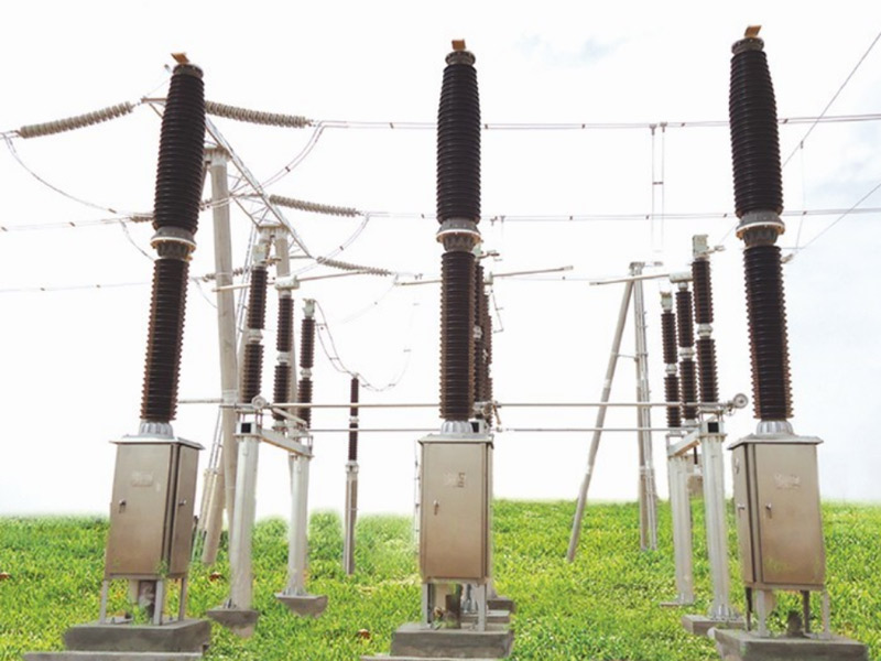
In the live tank circuit breaker, the enclosure that houses the contacts is energized, i.e., “live”. The dead tank circuit breaker’s contact enclosures are not energized and are connected to the ground grid. Live tank circuit breakers are less expensive than dead tank circuit breakers and require less space.
Live Tank Circuit Breaker
This type of circuit breaker has the interruption or switching (the opening/closing of contacts) occurring in an insulator (bushing) that is at potential or voltage above ground. Live tank breakers may seem simple (in terms of structure or parts) in construction but could have a higher voltage rating range compared with dead tank circuit breakers.
They are comparably cheaper and require less space relative to dead tank circuit breakers. If a project’s economics and space availability are constraints, then live tank circuit breakers are ideal for such a project. Manufacturers (for instance, General Electric) offer live tank breakers with a voltage from 72.5 kV to 800 kV.
Dead Tank Circuit Breaker
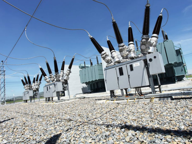
A circuit breaker is said to be a dead tank if the switching or interruption occurs within a tank at ground potential. In other words, the tank in which the opening and closing of contacts occur is at ground potential. The incoming and outgoing conductors are taken at the insulated bushings, as shown in the next figure.
Due to the construction of a dead tank circuit breaker, it is possible to install current transformers (CTs) within the bushings to measure current for protection and metering applications. It is relatively expensive compared to live tank circuit breakers of similar ratings.
The voltage range applications for a dead tank circuit breaker differ based on the manufacturer’s capability. For instance, General Electric offers high voltage dead tank circuit breakers that support applications up to 550 kV and can carry continuous current up to 5000 A.
As we can see, both the Live Tank Circuit Breaker and the Dead Tank Circuit Breaker are intended to be used as High Voltage Circuit Breakers, specifically on substations.
Low Voltage Circuit Breaker
So far, we have zeroed in on types of circuit breakers related to the generation, transmission, and distribution of electric energy: High Voltage Circuit Breakers and Medium Voltage Circuit Breakers.
However, the real leveraging of electric energy occurs in industries, facilities, commercial premises, and dwellings, where most devices work with low voltage, i.e., electrical components that work with less than 1000 volts between lines.
Motors for industrial machinery, variable frequency drives (and other Switching Mode Power Supplies), air conditioners, compressed air equipment, control equipment such as PLCs, IoT devices, appliances, lighting systems, and electrical tools, any of them are examples of electrical component working in low voltage and which is exposed at any given time to an electric overload, a short circuit between energized parts, or a line to ground fault.
The need to protect such electrical components and the electrical wiring in general against short circuits, and to protect the users of these facilities against an electric shock, is still present.
However, in this low-voltage environment, the current flow is lower and the extinction of the electric arc at the time of clearing a fault is less complicated than in medium-voltage and high-voltage circuit breakers.
A short circuit and a ground fault can occur in both a high voltage circuit and a low voltage circuit, but in the context of low voltage circuit breakers that we are addressing, protection becomes more necessary and deserves to be more complete because there is more low voltage electrical equipment that is used massively by a large number of people and users, generally not experts in electrical knowledge.
So, the current technology allows us to protect electrical equipment against a short circuit, a ground fault, or an electrical overload. For example, a current leak to the ground through an unforeseen path alerts us that people and equipment are in danger.
Since we will be going deeper into what a GFCI circuit breaker is (GFCI stands for ground fault circuit interrupter) let’s first clarify what a ground fault is according to NEC.
The NEC describes a ground fault as an unintentional, electrically conductive connection between an insulated grounded conductor of an electrical circuit and normally non-current-carrying conductors, metal enclosures, metal conduits, metal equipment, or earth.
The earth fault current at an early stage is very low, but if left unattended, it can easily reach a value much higher than the nominal load current. The earth fault current is also commonly known as residual current and zero sequence current. This is why earth fault protection devices (GFCI Circuit Breakers) are also known as residual-current devices (Residual Current Circuit Breaker, RCCB).
GFCI breakers
Electricity always wants to find a path to the ground. In a ground fault, electricity has found a path to the ground, but it is a path the electricity was never intended to be on, such as through a person’s body.
Because of this potential for electrical shock, the GFCI circuit breaker is used to protect people.
Occupational Safety and Health Administration OSHA defines GFCI as “A device intended for the protection of personnel that functions to de-energize a circuit or portion of a circuit within an established period of time when a current to ground exceeds some predetermined value that is less than that required to operate the overcurrent device (circuit breaker or fuse) of the supply circuit.”
The definition of a ground-fault circuit. interrupter is located in Article 100 of the NEC and is as follows: “A device intended for the protection of personnel that functions. to de-energize a circuit or portion thereof “.
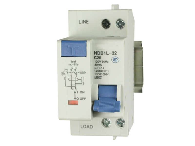
There are versions of GFCI circuit breakers from some manufacturers (for instance, ABB, Siemens) that integrate against short circuit capabilities, Electrical Overload protection, and ground fault surveillance in a single circuit breaker.
As we mentioned a few paragraphs above, a residual-current device (RCD), a residual-current circuit breaker (RCCB), and a ground fault circuit interrupter (GFCI) are different terms referring to what is basically the same device.
GFCI receptacle vs GFCI circuit breaker: A GFCI receptacle is integrated into an electrical outlet and it typically has a red (or possibly white) reset button on the outlet’s faceplate.
If the receptacle detects an electrical overload or imbalance, it trips off the circuit in a fraction of a second, and the small reset button pops, indicating that the electricity is no longer flowing.
GFCI receptacles are generally used instead of standard outlet receptacles to protect a single outlet location.
A GFCI Circuit Breaker installed in one of the service panel (breaker box) slots, adds GFCI protection to the entire circuit.
GFCI circuit breakers make more practical sense in situations where all outlets on a circuit require GFCI protection
GFCI breakers can be expensive, though, so this is not always the more economical option. Plus, it’s not always the most DIY-friendly option for homeowners uncomfortable working on a circuit breaker panel.
AFCI Breakers
An arc fault circuit interrupter (AFCI) or arc-fault detection device (AFDD) is a circuit breaker that breaks the circuit when it detects an electrical arc that is a signature of loose connections in home wiring. Loose connections can develop over time and sometimes become hot enough to ignite house fires.
Standard circuit breakers respond only to an overload or to a short circuit so they do not protect against arcing conditions that produce erratic, and often reduced current. AFCIs are devices designed to protect against fires caused by arcing faults in the home electrical wiring. The AFCI circuitry continuously monitors the current and discriminates between normal and unwanted arcing conditions. Once detected, the AFCI opens its internal contacts, thus de-energizing the circuit and reducing the potential for a fire to occur.
The electronics inside an arc fault circuit interrupter detect electrical current alternating at characteristic frequencies, usually around 100 kHz, known to be associated with wire arcing, and which are sustained for more than a few milliseconds. A combination AFCI breaker provides protection against parallel arcing (line to neutral), series arcing (a loose, broken, or otherwise high resistance segment in a single line), ground arcing (from line or neutral to ground), overload, and short circuit. The AFCI will open the circuit if dangerous arcing is detected.
When installed as the first outlet on a branch circuit, AFCI receptacles provide series arc protection for the entire branch circuit. They also provide parallel arc protection for the branch circuit starting at the AFCI receptacle. Unlike AFCI breakers, AFCI receptacles may be used on any wiring system regardless of the panel.
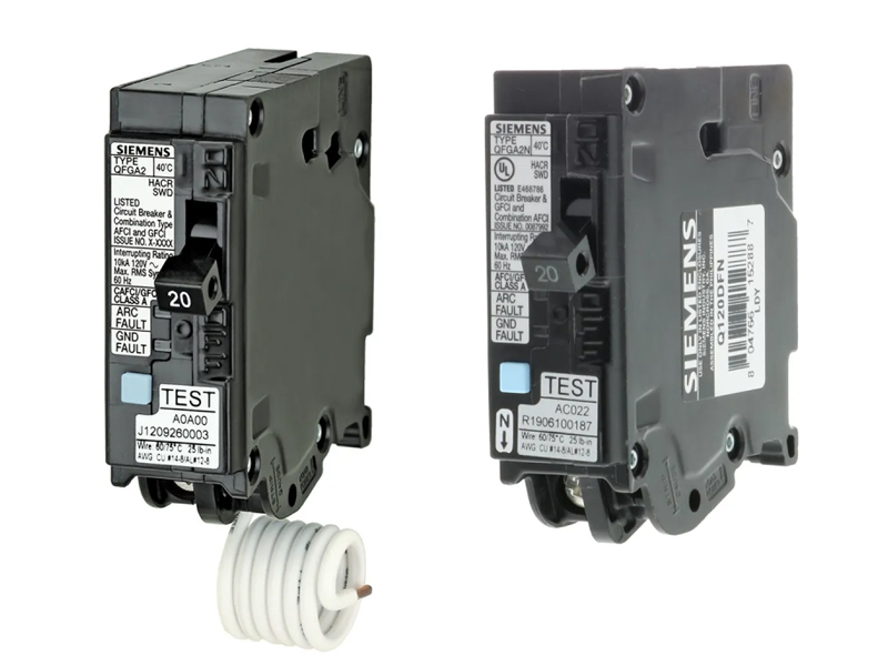
The figure above shows Siemens single pole breakers to be mounted on a breaker box. Dual Function, AFCI (arc faults) and GFCI (ground faults). Such breakers have an Interrupting Rating of 10 kA RMS symmetrical at 120 VAC (value to be considered if a short circuit occurs), and their current rating is 20 A.
Hydraulic-Magnetic Circuit Breakers
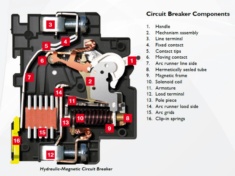
Hydraulic-Magnetic Circuit Breakers operate on the magnetic force produced by the load current flowing through a series-connected solenoid coil which is wound around a hermetically sealed tube containing an iron core, a spring, and a dampening fluid.
Normal Overload Operation
At currents below the circuit breaker rating, the magnetic flux in the solenoid is insufficient to attract the core toward the pole piece due to the spring pressure.
Where an overload occurs, i.e., currents above the circuit breaker rating, the magnetic flux in the solenoid produces sufficient pull on the core to commence its movement toward the pole piece. During this movement, the hydraulic fluid regulates the core’s speed of travel, thereby creating a controlled time delay, which is inversely proportional to the magnitude of the current. This time delay is useful in that if the overload is of short duration, i.e. start-up of motors, etc., the core returns to its rest position once the overload disappears.
If the overload persists, the core reaches the pole piece after a time delay particular to that current and in so doing, the reluctance of the magnetic circuit drops considerably, so that the armature is attracted to the pole face with sufficient force to collapse the latch mechanism (toggle) and consequently trip the breaker.
The contacts separate, the current ceases to flow, and the core returns to its resting position.
Short circuit operation
With high values of overloads or short circuits, the magnetic flux produced by the coil is sufficient to attract the armature to the pole face and trip the breaker even though the core has not moved. This is called the instantaneous trip region of the circuit breaker characteristic.
Unlike thermal circuit breakers, the hydraulic-magnetic circuit breakers’ trip point is unaffected by ambient temperature. After tripping, the breaker may be reclosed immediately since there is no cooling down time necessary.
By the nature of the principle of operation, it is possible to obtain any variation of time/current characteristics.
Advantages
- Always holds 100% rated current independent of ambient temperature
- Always trips at 125% or 130% of rated current depending on the product specification, independent of ambient temperature
- Immediate resetting after the trip
- Any current rating possible
- Large range of time delays possible
Miniature Circuit Breakers
Another circuit breaker type that is extensively used within standard circuit breakers for low voltage is the MCB, or miniature circuit breaker.
It is an automatically operated electromechanical device used for the protection of the circuit from overloading or short circuits. It breaks or opens the circuit when the current flowing through it exceeds its rated limit. MCB is used for the protection of low voltage circuits 240/415 v AC having a wide range of current ratings below 125V.
Miniature Circuit Breaker doesn’t trip (switch off) instantly. Instead, there is a time delay between fault occurrence and the breaking of contacts. Generally, they are designed to have a time delay of less than 2.5 milliseconds for short circuit and 2 sec to 2 min for overloading. It is to make sure the Circuit Breaker does not trip every time with momentary power surges or the starting of inductive loads due to high inrush current from such loads as electrical motors.
Tripping Mechanism in MCB
Miniature Circuit Breaker does not have adjustable trip characteristics. The breaking mechanism could be either thermal or thermal-magnetic when operating. The thermal breaking mechanism is used in case of overloading, while the magnetic breaking mechanism is used in case of short circuits.
MCB is enclosed in an insulating casing. The fixed and moving contacts made of copper or silver alloy connect with the two terminals for the current supply. There is an arc chute consisting of multiple conducting plates called arc splitters that dissipate the arc energy.
As far as arc quenching, the MCB (and MCCB, which we will discuss in the next paragraphs) work similarly to the air circuit breaker for medium and high voltage, as mentioned in the above paragraphs. While the operating mechanism is of two types: thermal and magnetic.
The thermal tripping mechanism consists of a bimetallic strip (made from two different metals having different thermal expansion), usually made from steel and brass, which is used for breaking the circuit in case of overloading. When the current above-rated limit starts flowing through the metallic strip, it heats up and starts expanding, which causes it to bend and trigger the latch to separate the contacts.
The magnetic tripping mechanism consists of a coil or solenoid that produces a magnetic field when current flows through it. In case of a short circuit or very high current, the solenoid produces a strong magnetic field to pull the lever and separate the contacts.
Molded Case Circuit Breaker MCCB
Molded Case Circuit Breaker is one of the most popular circuit breaker types and the most widely used low-voltage circuit breaker in different industries because its voltage and current ratings are more suited to the needs of industrial equipment.
It offers a thermal-magnetic tripping mechanism where the thermal mechanism is used for overloading and the magnetic is used for short circuit conditions. It can interrupt current around 10k – 200k amps, having very high current ratings up to 2500 Amps.
The best and most prominent part of MCCB is that its trip characteristics are adjustable in any current rating. MCB does not have such a feature. MCCB is suitable for applications where the normal current is above 100 amps. They are installed in industries.
MCCB can have fixed or interchangeable trip units. The trip unit is responsible for breaking the contacts upon meeting the fault condition. It provides three types of functions:
- Overloading:
Overloading occurs when the current exceeds a certain limit for a specific duration. Such current can damage the equipment and wiring and cause fire hazards. MCCB uses a bimetallic strip to protect against overloading.
The bimetallic strip is made of two types of metal having a different rate of heat expansion. The current flowing is used to heat the strip by either using a heater coil or directly conducting it through it. The strip heats up and bents thus tripping the mechanism.
- Short Circuit:
Short circuit current refers to the fault current in the system due to a downed line or broken exposed wires that come in contact or faulty equipment. The current flow due to short circuits is very large, far more than the overloading current.
Short circuit must be interrupted in the shortest period of time possible. MCCB can trip fault currents up to 10K-200K amps in the duration of 0.04 seconds.
- Manual Switching
MCCB can also act as a manual switch to switch ON/OFF the power supply to the circuit. It can manually break the power supply in case of emergency or maintenance.
That about wraps it up
In this post, we have gone through different circuit breaker types.
People, electrical installations, and multiple circuits can be scientifically and technically protected by using the suitable circuit breaker chosen in accordance with the current electrical regulations published by institutions such as UL, IEC, NFPA, CEN, and CENELEC. As far as electrical protection, the old adage is still valid: Safety First.
Sources
- https://www.electricaltechnology.org/2021/05/types-of-circuit-breakers.html (Cover Image)
- https://eepower.com/technical-articles/national-electrical-code-basics-overcurrent-protection-part-1/#
- https://www.electricaltechnology.org/2021/05/types-of-circuit-breakers.html
- https://www.c3controls.com/white-paper/understanding-different-circuit-breaker-types/ (Live and Dead Tank Circuit Breakers)
- https://shailearning.com/high-voltage-circuit-breakers/ (Live and Dead Tank Circuit Breakers)
- https://en.taikai.cn/workshop_1/17.html (Live Tank Circuit Breaker Image)
- https://www.lmz.com.tr/hv-circuit-breakers/ (Dead Tank Circuit Breaker Image)
- https://safeelectricity.org/ground-fault-circuit-interrupters-gfcis/ (ground fault according to NEC and GFCI breakers)
- https://guardiangfci.com/knowledge/gfci-defined (GFCI definition according to OSHA)
- https://www.sourceasi.com/shop/ndb1l-32c-20-120v-20-amp-gfci-circuit-breaker-120v-ac-30ma-earth-leakage-trip-curve-c-din-rail-mount-1378
- https://en.m.wikipedia.org/wiki/Arc-fault_circuit_interrupter
- https://cbibreakers.com/hydraulic-magnetic-principles (Hydraulic-Magnetic Circuit Breakers)
- https://www.siemens.com/us/en/products/energy/low-voltage/residential-circuit-breakers/residential-dual-fuction-circuit-breakers.html (Dual AFCI and GFCI Circuit Breaker Image)

