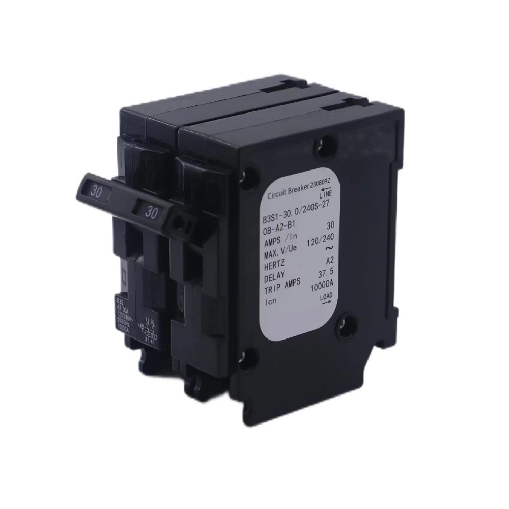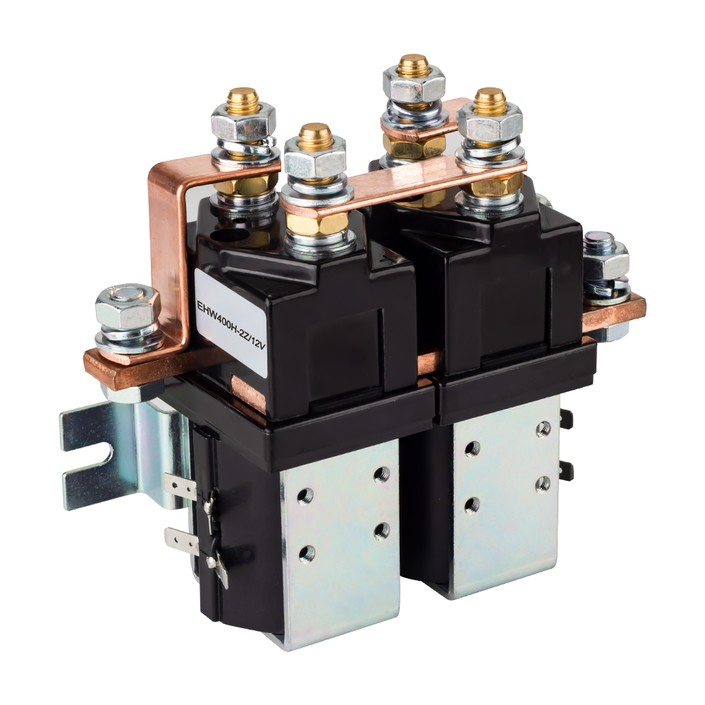
A solar disconnect switch is a critical safety device in photovoltaic (PV) systems that isolates power during maintenance, emergencies, or faults. By interrupting the flow of electricity between solar panels, inverters, and batteries, these switches protect equipment, operators, and first responders while ensuring regulatory compliance.
This guide covers types, working principles, sizing, installation, standards, and future smart switch trends for residential, commercial, and off-grid solar systems. So, let’s get started
What Does a Solar Disconnect Switch Do?
The solar disconnect switch is a main component of a photovoltaic system that provides control and safety. Its basic function is to quickly disconnect the electrical power produced by solar panels or the power delivered to the grid.
- ON Position: When the switch is in the ON position, the internal contacts are closed, allowing current to flow. Power is delivered from the solar panels to the inverter and then supplied to the grid or connected loads.
- OFF Position: When the switch is moved to the OFF position, the operating mechanism separates the contacts. This breaks the circuit completely, stopping current flow and electrically isolating the system.
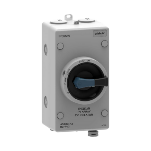
Solar panels continuously generate power during sunlight and may also produce power during grid outages, so the disconnect switch allows this power to be turned off easily when required.
Some main operations of solar disconnect switches are as follows:
1. System Shutdown
In conditions such as fire or electrical faults, the solar disconnect switch instantly stops the operation of the PV system. This high-speed circuit isolation helps prevent serious damage to equipment and reduces risk to human safety. These switches quickly break the circuit to protect the system.
2. Safe Maintenance
When system inspection, repair, or upgrades are required for electrical components such as wiring, inverters, or combiner boxes, disconnect switches isolate the circuits from the power flow. This minimizes the risk of sudden energization, electric shock, or arc flash, ensuring safe maintenance operations.
3. Arc Suppression
High voltages on the DC side of a solar system can cause dangerous arcs when circuits are opened under load. Some solar disconnect switches include arc suppression and arc interruption features, such as magnetic blowouts or arc chutes. These features effectively suppress arcs, reducing the risk of fire hazards and system damage.
4. First Responder Protection
Solar disconnect switches are installed in locations that are easily accessible during emergencies. This allows first responders to quickly de-energize the system, minimizing the risk of electrical shock or fire. Electrical codes require proper placement and labeling of disconnect switches to ensure safe and easy access for emergency personnel.
5. Grid Isolation
Solar disconnect switches allow the PV system to disconnect from the utility grid during outages or maintenance. This prevents unintended power flow back into the grid, which could be hazardous for utility workers and connected equipment. Proper grid isolation also helps maintain stable system operation when grid abnormalities occur.
PV System Power Flow Process (Grid-Tied)
The core energy path is as follows:
Sunlight → PV Array → Combiner → DC Disconnect → Inverter → AC Disconnect → Distribution Panel → Meter → Utility Grid

1. PV Array (Solar Panels)
At the top of the building is the PV Array, where sunlight strikes silicon cells and generates Direct Current (DC) electricity through the photovoltaic effect.
2. Combiner Box (DC Collection)
The DC output from multiple solar strings flows into a Combiner Box, where circuits are combined into a single DC output.
This stage:
- Simplifies wiring
- Provides string-level protection
- May include fuses and surge protection
3. DC Disconnect (Isolation & Safety)
The electricity then passes through the DC Disconnect, a safety isolation device that allows the solar array to be manually shut off for maintenance or emergency situations.
This component is required by electrical codes and ensures safe servicing of the inverter and downstream equipment.
4. Inverter (DC to AC Conversion)
Next, DC electricity enters the Inverter, where it is converted into Alternating Current (AC).
The inverter also performs:
- Grid synchronization
- Anti-islanding protection
- System monitoring
5. AC Disconnect (Utility Accessible)
After conversion, the power flows through an AC Disconnect, which allows utility companies to isolate the solar system from the grid if necessary. This ensures safe interconnection and regulatory compliance.
6. AC Distribution Panel and Meter
Finally, electricity enters the building’s AC distribution system.
- The main panel distributes power to loads.
- A bi-directional meter measures imported and exported energy.
- Through net metering (where applicable), users are billed based on net energy consumption.
At this stage, solar power is fully integrated with the building and the grid.
Key Components of a Solar Disconnect Switch
The solar disconnect switch consists of several components, each performing a specific function, as outlined below:
Switch Contacts
Switch contacts are the current-carrying parts of the disconnect switch.
- When the switch is in the closed position: The contacts are connected and allow current to flow through the circuit.
- When the switch is open: The contacts are separated, stopping current flow completely.
The contacts in solar disconnect switches are typically made of silver alloys, which offer high conductivity, arc resistance, and effective heat management during electrical faults.
Operating Handle or Lever
The operating handle provides manual control of the switch, allowing it to be moved between ON and OFF positions. Many handles include a position indicator to show whether the circuit is energized or isolated clearly. To prevent partial switching or accidental operation, these handles are designed with strong mechanical locking and protection mechanisms.
Arc Extinguishing Mechanism
Interrupting DC can generate electrical arcs between separating contacts. The arc extinguishing mechanism suppresses and safely eliminates these arcs to protect the switch and system. Common arc suppression techniques include arc chambers that stretch and cool the arc, magnetic blowouts that drive the arc away from contacts, and specially designed contact geometries that increase arc extinction speed.
Enclosure
The enclosure protects the internal components of the disconnect switch. It is designed to withstand environmental conditions such as moisture, rain, dust, and ultraviolet (UV) radiation from sunlight, ensuring reliable outdoor operation.
Terminals and Cable Connections
Terminals and cable connections provide secure electrical connections between the switch and system wiring. Properly designed terminals reduce contact resistance and heat generation, ensuring stable and continuous operation.
They also accommodate different conductor sizes and allow correct torque application for safe, long-term connections.
Cable Glands
Cable glands seal the cable entry points of the enclosure, preventing water, dust, and moisture from entering the switch. They also provide strain relief for the cables to ensure stable electrical connections in outdoor environments.
Lockout Provision (Optical)
The lockout provision allows the switch to be locked in the OFF position using a padlock. This feature is essential during inspection and maintenance, as it prevents accidental re-energization of the system and enhances worker safety.
Types of Solar Disconnect Switches
Different types of disconnect switches are designed to handle specific system voltages, currents, and operational requirements, ranging from small residential arrays to large utility-scale solar farms. Understanding the characteristics and applications of each switch type is essential for proper system design, compliance, and long-term reliability:
DC Disconnect Switches
DC disconnect switches are installed between the solar panels and the inverter to manage the direct current generated by the PV arrays. These switches are designed to safely interrupt high-voltage DC power and provide isolation for maintenance, safety, and system protection.
These switches are available in a variety of voltage ratings, including 600 VDC, 1000 VDC, 1200 VDC, and 1500 VDC. Current ratings commonly range from 32 A, 63 A, 125 A, 250 A, and higher, depending on system requirements. They are offered in multiple pole configurations to suit different circuit designs.
DC disconnect switches are also built to withstand harsh outdoor environments. Their environmental ratings include IP65, IP66, IP67, and NEMA 4X, ensuring strong resistance to dust, corrosion, and extreme weather conditions.
AC Disconnect Switches
These switches are connected between the inverter and the utility connection to control the AC output of the inverter. AC disconnect switches are easier to design than DC disconnects because alternating current naturally passes through zero voltage multiple times per second, which simplifies arc interruption.
AC disconnect switches must be installed in a location that is easily accessible at all times to utility personnel and first responders to ensure safe and rapid system shutdown during maintenance or emergency situations.
For outdoor installations, AC disconnect switches are required to have a minimum NEMA 3R enclosure rating to provide adequate protection against rain and environmental exposure.
Fused Disconnect
Fused disconnects are typically installed on PV arrays or energy storage systems. They provide built-in overcurrent protection, reducing the need for a separate fuse holder.
Non-fused Disconnect
Non-fused disconnects provide simple isolation without integrated protection. They are lower in cost and are suitable only for small systems that have external protection devices.
Manual Disconnect
Manual disconnect switches are commonly used in residential or commercial PV systems. They feature simple toggle or knife mechanisms and require onsite operation.
Automatic / Load-break Disconnect
Automatic or load-break disconnects are designed for utility-scale PV installations. They can be operated remotely or motorized, enabling rapid response and system monitoring.
Installation Location in Solar PV Systems
- DC Disconnects: Connected in sight of the inverter, about 6 feet away
- AC Disconnects: Easy access to utility personnel, located close to the meter
- Height Requirements: The operating handle is a maximum of 6.5 feet above the ground
- Clear Working Space: 3 feet of clearance in front of the disconnect
- Lockout Features: Accommodate lockout/tagout process
Required Sizing Calculations
For accurate sizing, proper calculations are made for the system.
DC Disconnect Sizing Equation
Minimum Current Rating = Short-Circuit Current (Isc) * 1.25
Minimum Voltage Rating = Open-Circuit Voltage (Voc) * 1.25
Example Calculation
Given:
- Array Short-Circuit Current = 30 A
- Array Open-Circuit Voltage = 350 V
Step 1 – Current Rating:
Disconnect Current Rating=30A×1.25=37.5A
40 A or 50 A DC disconnect switch is best to use
Step 2 – Voltage Rating:
Disconnect Voltage Rating=350V×1.25=437.5V
600 V DC-rated disconnect recommended
Technical Parameters
Voltage Rating
The size should be 25% of the maximum system voltage for safety:
- 600 VDC = small residential
- 1000 VDC = standard residential
- 1200VDC = medium commercial
- 1500 VDC = large commercial
Current Rating
Continuous rating ≥ 125% of maximum array current.
Typical ratings: 32 A, 63 A, 125 A, 250 A, or higher.
Breaking Capacity
The switch must safely interrupt fault currents. The making capacity should be verified for closing during fault conditions.
Typically ranging from 4,000 A to 10,000 A.
Pole Configuration
Number of separate circuits the switch can isolate:
- 2-pole = single string
- 4-pole = dual strings
- 6-pole = three strings
- 8-pole = four strings
More poles for larger arrays
Environmental / Enclosure Rating
IP65 = dust-tight
IP66 = powerful water jets
IP67 = temporary immersion dust-tight
NEMA 4X = corrosion-resistant, best for outdoor/marine
Standards, Codes, and Certifications
|
Types
|
Standard / Code
|
Description
|
|
Electrical Codes
|
NEC (NFPA 70) – Article 690
|
PV system disconnecting and switching requirements
|
|
NEC 690.13
|
PV system DC disconnect needed
|
|
|
NEC 690.15
|
Equipment disconnection
|
|
|
NEC 690.17
|
Switch is DC-rated and load-break capable
|
|
|
NEC Article 705
|
Connected with utility power
|
|
|
Safety Standards (USA)
|
UL 98
|
Enclosed and dead-front safety switches
|
|
UL 508i
|
PV-specific DC disconnect switches
|
|
|
UL 508A
|
Industrial control panels have PV disconnects
|
|
|
UL 50 / 50E
|
Enclosure construction and environmental protection
|
|
|
International Standards
|
IEC 60947-3
|
Switch-disconnectors & load-break switches
|
|
IEC 60364-7-712
|
PV system installation requirements
|
|
|
EN 60947-3
|
European adoption of the IEC standard
|
|
|
Environmental Ratings
|
NEMA 3R
|
Outdoor, rain-resistant enclosure
|
|
NEMA 4 / 4X
|
Watertight & corrosion-resistant enclosure
|
|
|
IP65 / IP66
|
Dust-tight and water-resistant enclosure
|
|
|
Utility Requirements
|
Local AHJ Rules
|
Location, labeling, and lockout rules
|
|
Utility Interconnection Standards
|
Utility-specific disconnect features
|
|
|
Certification Markings
|
UL Listed
|
Field installation
|
|
cUL / cULus
|
Certified for Canada and the USA
|
|
|
CE Marking
|
European conformity
|
|
|
IEC Certification
|
Compliance with international standards
|
|
|
Labeling & Accessibility
|
NEC 690
|
Accessible and clearly labeled
|
|
NEC 690.13(E)
|
Lockable in the open (OFF) position
|
Applications by System Type
Choosing the right solar disconnect switch is essential for the safe and reliable operation of a photovoltaic (PV) system. Residential, commercial, and off-grid/RV installations have different voltage, current, and operational requirements, making proper switch selection critical for maintenance, emergency shutdown, and system protection.
The following sections outline key considerations and recommended disconnect solutions for each system type.
Residential Systems
Residential solar systems typically range in size from 5 to 20 kW and operate at voltages between 300 and 600 VDC, with current levels generally in the range of 20 to 50 A. These systems often require compact enclosures with an aesthetically pleasing appearance suitable for residential environments.
The recommended solution for residential installations is the use of integrated DC disconnects built into residential inverters, along with compact, space-saving enclosures and disconnect switches rated for residential applications.

Commercial Systems
Commercial solar systems commonly operate at higher voltages, typically between 1000 and 1500 VDC, and handle current levels ranging from 100 to 800 A. These installations often involve multiple PV arrays, requiring the use of multi-pole disconnect switches to isolate individual strings or array sections.
Adequate maintenance access and working clearances must be provided for service personnel. The recommended solution for commercial systems includes heavy-duty, DC-rated disconnect switches, multi-pole configurations for string isolation, and lockable, clearly labeled enclosures designed for industrial environments.

Off-Grid and RV Systems
Off-grid and RV solar systems require electrical isolation for both the PV input and the battery storage systems. These applications typically impose strict design constraints, including compact size and lightweight construction, due to limited space and mobility requirements.
Environmental factors such as vibration and movement require vibration-resistant mechanical designs. Multiple disconnect points are necessary, with separate disconnect switches for batteries, solar inputs, and loads.
The recommended solution for these systems includes battery-rated DC disconnect switches and modular disconnect units that allow flexible system configuration.

How to Choose the Right Solar Disconnect Switch
Factors to consider:
- Voltage and Current Ratings: Ensure match with PV string voltage and inverter output.
- AC vs DC Operation: DC disconnects must handle arcing challenges of direct current.
- Fused vs Non-Fused: Choose based on need for overcurrent protection.
- Environmental Suitability: IP/NEMA rating, temperature range, UV resistance.
- Ease of Operation: Manual or remote operation depending on accessibility.
- Maintenance Requirements: Simple designs reduce downtime and inspection complexity.
Common Problems and Troubleshooting
Contact Wear and Damage
Solar disconnect switch contacts wear over time. Common signs of wear include:
- Increased operating force, making switch operation difficult.
- Arcing during operation, which may cause burning smells.
- Discoloration of contacts, often turning black.
- Interruption of power supply due to damaged or discolored contacts.
Environmental Effect Assessment
Different environmental factors also affect solar disconnect switches. For example, prolonged exposure to ultraviolet (UV) light can damage plastic enclosures over time.
Moisture and salt air can cause corrosion on terminals and contacts. Temperature variations, heating, cooling, and repeated cycles increase mechanical stress on switch components.
Maintenance Recommendations
- Inspections: Perform regular visual inspections of connections and mounting. Ensure that terminals are firmly connected. Check proper labeling and accessibility, and perform no-load condition tests.
- 5-Year Service: Disconnect the system and perform a detailed inspection of components. Clean and lubricate parts as required. Replace components if any damage is found. Update labels as needed to comply with current code requirements.
Future Trends in Solar Disconnect Technology
Solar energy systems are evolving rapidly, and modern disconnect switches are no longer just simple isolation devices. Today’s smart disconnect switches combine advanced safety features, intelligent monitoring, and regulatory compliance to ensure efficient, reliable, and safe solar operations.
Smart Disconnect Switches
- Remote Monitoring – Modern smart disconnect switches offer real-time status reporting and fault detection, enabling operators to monitor system health from anywhere.
- Automated Operation – These switches support remote switching for maintenance or emergency situations, reducing the need for manual intervention.
- Predictive Maintenance – AI-powered analysis allows the system to assess performance, predict wear, and alert operators before failures occur.
- Energy Management Collaboration – Smart switches integrate seamlessly with battery storage and load management systems, optimizing energy usage and efficiency.
Enhanced Safety Features
- Arc Fault Detection – Built-in sensors detect hazardous arcing conditions, protecting both equipment and personnel.
- Ground Fault Integration – Combining GFCI and disconnect functions provides comprehensive protection against electrical faults.
- Rapid Shutdown Enhancements – High-speed response times and module-level control ensure quick and safe shutdown in emergencies.
- First Responder Communication – The system can connect with emergency response networks to enhance safety during critical situations.
Regulatory Evolution
- NEC 2026 Updates – New code requirements mandate changes to rapid shutdown and arc fault protections for solar installations.
- International Harmonization – IEC standards are evolving to ensure global compatibility of solar disconnect switches.
- Utility Integration – Emerging features support grid-interactive solar systems, enabling smarter energy flow and management.
- Energy Storage Integration – Updated codes improve compatibility and safety for battery-coupled solar systems, aligning with modern energy storage needs.
Conclusion
Accurate selection and proper connection of a solar disconnect switch are key factors for the safe and reliable operation of a photovoltaic (PV) system. These safety components protect electrical circuits from faults, isolate power during maintenance, and provide protection for installers, maintenance personnel, and first responders during emergency or abnormal operating conditions. A correctly rated DC disconnect switch provides controlled isolation of high-voltage DC power and minimizes the risk of electric shock, arcing, and equipment damage.
Several factors are important for safe and long-term operation, including system voltage and current ratings, regulatory compliance, environmental conditions, and correct installation practices.
Different regulatory standards, such as IEC and NEC, require DC isolator switches with features including proper labeling, lockability, and the ability to interrupt load current. Products such as ELEHUB DC disconnector switches—32A 1200V DC isolator switches with IP66-rated enclosures for outdoor installations and 1500V DC, 4-pole isolator switches for higher-voltage commercial systems—meet these requirements.
ELEHUB also offers DIN-rail-mounted DC disconnector switches that are ideal for compact inverter panels and combiner boxes where easy installation and space efficiency are required. By selecting Elehub DC isolator switches according to system ratings and environmental conditions, ensuring correct wiring, and following PV system codes, reliable operation and long-term safety can be achieved.
FAQs
What’s the difference between AC and DC solar disconnect switches?
DC disconnects connected between solar panels and inverters that manage direct current make arc interruption challenging. It needed certain connection materials and arc suppression methods. AC disconnects are connected between inverters, and the utility connection manages AC that flows zero about 120 times in a single second. make easy functions; both are part of grid-tied systems.
Are rapid shutdown devices needed for all solar installations in 2026?
According to NEC 2023 requirements, all PV systems come with an abrupt shutdown operation that minimizes voltage at a safe value in 30 seconds. This occurs with module-level devices and string-level shutdown components.
Module-level devices are part of the new installation since they offer high-value safety.
What is the difference between a circuit breaker and a disconnect switch?
A switch is used for an on and off power supply, while a circuit breaker breaks the circuit when any electrical faults, like short circuits or overloading, occur.