A Battery Management System (BMS) represents the sophisticated electronic control unit that governs every aspect of modern battery pack operation.
At its core, a BMS is a specialized computer system designed to monitor, control, and protect rechargeable battery assemblies, particularly the DC power systems that store and deliver electrical energy in everything from smartphones to massive grid storage installations.
Battery packs operate exclusively on Direct Current (DC) power, where electrons flow consistently in one direction from the battery’s negative terminal to its positive terminal.
This DC nature creates unique challenges and requirements that Battery Management Systems must address through specialized DC electrical components and control circuits.
What Is a Battery Management System
A BMS serves multiple critical functions: it acts as a protective guardian, preventing dangerous operating conditions, a performance optimizer maximizing energy delivery, and an intelligent coordinator managing power flow between the battery and external DC or AC systems.
The system continuously processes data from dozens of sensors while making split-second decisions that can mean the difference between safe operation and catastrophic failure.
The Core Purpose and DC System Integration

Source: https://www.linkedin.com/pulse/understanding-role-specifications-battery-management-system-chan
Battery Management Systems primarily exist to address the inherent challenges of managing DC power storage at scale. Unlike AC electrical systems, where power alternates direction, DC battery systems maintain constant voltage polarity and current direction, creating specific monitoring and control requirements.
Modern battery packs contain dozens or hundreds of individual cells connected in series and parallel configurations. Each cell exhibits slightly different characteristics due to manufacturing tolerances, aging patterns, and environmental conditions.
Without proper management, these differences can lead to cell imbalances, overcharging, overheating, and potentially dangerous thermal runaway events.
The BMS prevents these problems by acting as an intelligent intermediary between the battery pack and the device it powers. It communicates with charging systems, motor controllers, and vehicle computers to coordinate energy flow while maintaining safe operating conditions.
Key DC Electrical Components and Hardware Architecture
Battery Management Systems incorporate specialized DC electrical components designed to handle the unique characteristics of Direct Current power systems. Understanding these DC-specific components reveals how modern BMS technology manages high-voltage DC battery packs safely and efficiently.
DC Voltage Monitoring Circuits
They form the foundation of any BMS, specifically designed to measure the DC voltage levels of individual battery cells. These circuits use high-precision analog-to-digital converters (ADCs) with DC-coupled input stages and precision DC voltage references to measure personal cell voltages with millivolt accuracy.
Advanced BMS designs utilise differential amplifiers with DC common-mode rejection and multiplexing circuits to simultaneously monitor hundreds of DC cells, while maintaining galvanic isolation between measurement circuits and high-voltage DC battery connections.
DC Isolation Circuits
These protect low-voltage BMS electronics from high-voltage DC battery systems using optocouplers, digital isolators, and isolated DC-DC converters. These components prevent ground loops and electrical interference, allowing for safe communication between the high-voltage DC battery pack and low-voltage control circuits.
DC Current Sensors

The sensors measure the flow of Direct Current into and out of the battery pack using specialized DC measurement techniques. Hall effect current sensors detect the magnetic field created by DC flow without requiring electrical contact with the high-voltage DC circuit.
DC shunts provide precise measurement through voltage drop across calibrated DC resistors. These DC measurements enable the BMS to calculate the state of charge, monitor DC power consumption, and prevent DC overcurrent conditions.
DC Power Switching Components
These components control the flow of high-voltage Direct Current within the battery system. High-voltage DC contactors utilise electromagnetic coils to open and close DC circuits, whereas solid-state electrical switches offer faster switching with reduced mechanical wear.
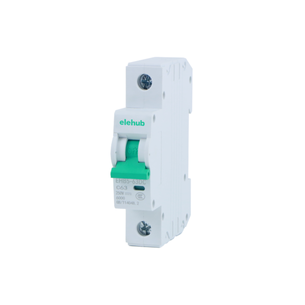
DC circuit breakers and DC fuses provide overcurrent protection specifically designed for Direct Current applications, where arc suppression becomes more challenging than in AC systems.
DC-DC Converters
The converters within the BMS provide regulated low-voltage DC power for control circuits from the high-voltage DC battery pack.
These isolated DC-DC converters step down battery voltage to power microcontrollers, sensors, and communication circuits while maintaining electrical isolation. Buck converters, boost converters, and flyback converters represent common DC-DC converter topologies used in BMS designs.
DC Cell Balancing Circuits
They address the natural tendency for DC cells to develop different charge levels over time within series-connected DC battery strings. Passive DC balancing systems use precision resistors and MOSFETs to discharge higher-voltage cells, dissipating excess energy as heat.
Active DC balancing systems transfer DC energy between cells using inductors, capacitors, or transformers in flyback, forward, or resonant converter configurations. These DC-to-DC energy transfer circuits enhance overall battery pack capacity and extend the lifespan of the DC system.
High-Voltage DC Protection Switches
The switches enable the disconnection of the DC battery pack from external circuits when hazardous conditions are detected. DC contactors designed for high-voltage battery applications utilize special arc suppression techniques, as DC arcs are more difficult to extinguish than AC arcs. Pyrotechnic DC disconnect switches provide emergency isolation by physically separating DC connections using explosive charges.
DC System Challenges and BMS Solutions
Managing Direct Current battery systems presents unique challenges that differ significantly from AC electrical systems. DC circuits lack the natural zero-crossing points that AC systems use for arc extinction, making DC switching more complex.
DC voltage levels remain constant rather than varying sinusoidally, requiring different measurement and monitoring approaches.
DC Arc Suppression

Source: https://hyteps.com/simulations/arc-flash-calculations/
This represents one of the most significant challenges in high-voltage DC battery systems. When DC contacts open under load, sustained arcs can form that are difficult to extinguish.
BMS designs incorporate specialized DC arc detection circuits that monitor for arc signatures and coordinate with DC switching devices that use magnetic blowout, vacuum switching, or SF6 gas to suppress DC arcs.
DC Ground Fault Detection

Source: https://theengineeringmindset.com/ground-neutral-and-hot-wires-us-can/electric-shock-ground-fault/
It requires specialized monitoring since DC systems don’t have the neutral reference that AC systems provide. BMS circuits inject small AC test signals into the DC system or use active measurement techniques to detect insulation breakdown between the high-voltage DC battery and chassis ground.
DC Ripple and Noise Management
It is critical in DC battery systems where switching converters and motor controllers can inject high-frequency noise into the DC bus. BMS designs incorporate DC filtering circuits using capacitors and inductors specifically tuned for DC applications, along with common-mode chokes to suppress electromagnetic interference.
Safety Functions and DC Protection Features
Safety represents the most critical function of any Battery Management System, particularly when managing high-voltage DC power systems.
DC battery packs store significant amounts of energy and can become dangerous if operating conditions exceed safe limits. The BMS implements multiple DC-specific protective measures to prevent hazardous situations.

1. DC Overvoltage Protection prevents individual cells from exceeding their maximum safe DC voltage during charging.
When the BMS detects cells approaching their DC voltage limit, it reduces charging current using DC current control circuits or disconnects the charger entirely through high-voltage DC contactors. This protection prevents lithium plating, gas generation, and potential fire hazards in DC battery systems.
2. DC Undervoltage Protection prevents deep discharge that can permanently damage DC battery cells. The BMS monitors individual cell DC voltages during discharge and reduces power output through DC switching circuits or disconnects the load when cells approach their minimum safe DC voltage.
3. DC Overcurrent Protection limits the rate of DC energy flow into or out of the battery pack using high-speed current monitoring and DC switching devices.
The BMS monitors charging and discharging DC currents, reducing power when limits are approached and disconnecting the DC circuit through contactors or solid-state switches if dangerous current levels are detected.
4. Thermal Management represents one of the most complex safety functions. The BMS monitors temperatures throughout the battery pack and coordinates with cooling systems to maintain optimal operating conditions.
If temperatures exceed safe limits, the BMS can reduce power output, activate cooling systems, or shut down the battery entirely.
5. DC Isolation Monitoring checks for electrical faults that could create dangerous conditions in high-voltage DC battery systems.
The BMS continuously monitors insulation resistance between the positive and negative DC terminals of the battery system and the vehicle chassis or device housing. DC isolation monitoring circuits inject small test currents or voltages to measure insulation resistance without affecting regular DC battery operation.
State Estimation and DC Battery Analytics
Modern Battery Management Systems perform sophisticated calculations to estimate the DC battery’s condition and predict its future performance. These analytics enable optimal charging strategies and provide valuable information about the DC energy storage system status.
1. State of Charge (SOC) Estimation determines the amount of DC energy remaining in the battery pack through precise monitoring of DC voltage levels and current integration.
The BMS uses coulomb counting of DC flow, DC voltage measurements, and complex algorithms to estimate SOC with high accuracy.
2. State of Health (SOH) Assessment tracks DC battery degradation over time by monitoring changes in DC internal resistance, capacity fade, and charging efficiency.
The BMS analyzes DC voltage recovery curves, impedance spectroscopy measurements, and DC power capability to estimate remaining battery life.
3. State of Power (SOP) Calculation determines how much DC power the battery can safely deliver or accept at any given moment. The BMS considers individual cell DC voltages, temperatures, and DC current capabilities to calculate maximum power limits for both charging and discharging operations in DC systems.
Communication Protocols and DC System Integration
Battery Management Systems must communicate with various external devices and systems to coordinate operation and share critical information about the DC power system status. Multiple communication protocols enable this integration while maintaining safety and reliability in high-voltage DC environments.
CAN Bus Communication provides the primary interface between the BMS and vehicle or device controllers, transmitting real-time DC voltage, current, and power information. Controller Area Network protocols enable real-time data exchange about battery status, DC power limits, and safety conditions.
DC Charging Communication Protocols coordinate battery charging with external DC charging equipment. ISO 15118, CHAdeMO, and CCS standards enable the BMS to communicate DC battery capabilities, charging curves, and safety limits to DC fast charging stations.
These protocols negotiate DC power levels, monitor DC charging safety conditions, and coordinate emergency shutdown procedures.
BMS Applications Beyond Electric Vehicles
While electric vehicles receive significant attention, Battery Management Systems enable battery applications across numerous industries and use cases.
Grid Energy Storage systems use large-scale BMS installations to manage megawatt-hour battery arrays. These systems coordinate with electrical grids to provide services such as frequency regulation, peak shaving, and the integration of renewable energy.
Grid-scale BMS designs must handle thousands of cells while maintaining high reliability and long operational lifespans.

Residential Energy Storage brings BMS technology to home solar and backup power systems. These systems manage daily charge-discharge cycles while providing backup power during outages. Home BMS designs balance performance, cost, and user-friendly operation.
Marine and Aviation Applications require BMS designs that meet strict safety and reliability standards. These systems must operate in challenging environmental conditions while providing the high reliability needed for critical transportation applications.
Emerging DC Technologies
Battery Management System technology continues to advance in meeting the demands of larger DC battery systems, new battery chemistries, and emerging applications that require more sophisticated DC power control.
Silicon Carbide (SiC) and Gallium Nitride (GaN) DC Components represent the next generation of power semiconductor devices for BMS applications. These wide-bandgap semiconductors enable DC switching at higher voltages, currents, and frequencies while generating less heat than traditional silicon devices.
Advanced DC Arc Detection and Suppression technologies use machine learning algorithms to identify arc signatures in DC circuits and coordinate rapid suppression responses. These systems combine multiple sensing techniques to detect DC arcs within microseconds and activate suppression systems before significant damage occurs.
Also, machine learning algorithms can identify subtle patterns in battery behavior that traditional algorithms might miss. In the near future, AI-powered BMS designs can adapt their control strategies based on specific usage patterns and environmental conditions.
Battery Management Systems represent one of the most critical yet often overlooked technologies enabling our transition to electrified transportation and renewable energy storage.
As battery applications continue to expand and energy storage requirements grow, BMS technology will continue to evolve to meet new challenges while maintaining the safety and reliability that make modern battery systems possible.
Understanding how these systems work provides insight into the sophisticated engineering that makes our electrified future practical and safe.
Related Articles
BESS Safety 101: Standards and Risks
What is a BESS Container? The Heart of Modern Energy Storage