A conventional transformer does one job well. It changes voltage through electromagnetic induction. Yet it can’t steer power, regulate frequency, create a DC connection, suppress harmonics, or communicate with a grid controller. Those limits are more obvious as distribution networks absorb solar arrays, batteries, EV chargers, data centers, and bidirectional loads.
A solid-state transformer, or SST, tackles the problem differently. It combines semiconductor switching stages, digital control, and a high- or medium-frequency isolation transformer to convert as well as manage electrical power.
That extra circuitry comes at a price – literally and technically. An SST isn’t yet the sensible replacement for every utility transformer. Where active power control, compact packaging, DC integration, or rapid grid support carries real value, it can do far more than alter a voltage ratio.
What Is a Solid-State Transformer?
A solid-state transformer (SST), also known as a power electronic transformer (PET), is a power conversion system that combines voltage transformation, galvanic isolation, and active power control. Unlike a conventional 50/60 Hz transformer, it performs most voltage conversion through controllable semiconductor converters.

Solid-State Transformer Exploded View
Source: YouTube @EPFL
Depending on its topology, it can connect:
- Medium-voltage AC to low-voltage AC
- Medium-voltage AC to low-voltage DC
- Medium-voltage DC to low-voltage DC
- AC and DC sources through multiple controlled ports
Unlike a line-frequency transformer, an SST first changes the incoming waveform into a form that is suitable for semiconductor control. The energy is then transferred through a compact medium-frequency isolation transformer before being converted into the required AC or DC output.
The U.S. Department of Energy explains the traditional SST arrangement as front-end and back-end converters that are coupled through an isolation transformer. Its high-frequency link permits higher power density. At the same time, the converters can support bidirectional power transfer, AC or DC ports, and active frequency and voltage regulation.
The word “solid-state” shouldn’t create the wrong picture, though. An SST still contains magnetic components, capacitors, busbars, cooling hardware, sensors, insulation, and mechanical switching devices. The name shows its massive use of controllable semiconductor switches.
Solid-State Transformer Architecture
A solid-state transformer architecture extends well beyond the three main conversion stages.

Solid-State Transformer Exploded View
Source: YouTube @EPFL
Modular Power Cells
Directly exposing one semiconductor bridge to an entire medium-voltage feeder would demand tremendously high blocking voltage. However, modular multilevel and cascaded-cell architectures divide that electrical stress among repeatable converter modules.
Cells can be connected in series on the high-voltage side and in parallel where more current is needed. Modularity also opens the door to redundancy. A controller may bypass a failed cell and continue at decreased capacity rather than shutting down the complete system.
Just as an example, using five stacked 1.44 kV, 10 kVA modules, an ORNL research prototype was able to create a 7.2 kV, 50 kVA SST. For the purpose of storage, renewable energy production, or electric vehicle charging, it had MVAC, LVAC, and LVDC ports.
Medium-Frequency Magnetic Stage
Materials may include ferrite, amorphous alloy, or nanocrystalline material. It is picked according to flux density, switching frequency, core loss, temperature, and cost. Litz wire, copper foil, coaxial arrangements, or interleaved windings can reduce AC resistance and leakage inductance.
One 5 kV research transformer accomplished 0.13% leakage inductance and 15 kV insulation using coaxial cables and nanocrystalline cores. There is a strong connection between electromagnetic design and dielectric design, as shown by this example.
Digital Control and Communications
Sensors measure current, voltage, temperature, insulation condition, and module health. Following that, a digital controller manages modulation, cell-voltage balancing, soft switching, power direction, port priorities, reactive power, and fault response.
Communication links can connect the SST to a distribution management system, microgrid controller, building energy platform, or SCADA network. That capability makes it a controllable grid node but, remember, it also introduces software validation and cybersecurity duties.
Auxiliary and Protection Systems
Gate drivers need isolated power and dependable communication whenever operating over high-voltage barriers. Cooling might be forced-air, liquid-based, or cold-plate assisted. Fuses, breakers, contactors, isolators, shunts, surge protection, discharge paths, pre-charge circuits, and grounding supervision are the components that round off the assembly.
How Do Solid-State Transformers Work?
A common three-stage solid-state transformer working principle can be followed beginning with the medium-voltage input and continuing all the way up to the end load.
A typical power path might be the following:
MVAC input → active rectifier → MVDC link → isolated high-frequency DC/DC stage → LVDC link → inverter or DC output

of a Solid-State Transformer (SST) Diagram
Source: The Fusion Report
1. The input stage conditions grid power
An active rectifier converts incoming AC power into controlled DC. Unlike a simple diode bridge, it can shape input current, correct power factor, regulate the DC-link voltage, exchange reactive power, and limit fault current.
In MV SSTs, series-connected converter cells distribute voltage stress across semiconductor modules.
2. The DC link decouples both sides
The DC link creates an intermediate bus between grid-side and load-side converters, allowing independent control and reducing the impact of input disturbances on output power.
Newer SST designs may replace large electrolytic capacitors with active power-decoupling circuits to reduce size and improve lifetime.
3. Semiconductors create a high-frequency waveform
Bridge converters switch DC-link voltage at kilohertz frequencies to create high-frequency AC. The higher frequency reduces transformer size and improves power density.
Silicon carbide (SiC) devices enable higher-voltage, higher-frequency operation with lower losses. An ORNL design used 3.3 kV SiC MOSFETs in a bidirectional 5 kV, 50 kVA SST interface.
4. A medium-frequency transformer provides isolation
The high-frequency waveform passes through a compact transformer that provides voltage conversion and galvanic isolation between MV and LV sections.
Although smaller than conventional transformers, it must withstand fast voltage transitions, partial discharge, parasitic capacitance, thermal cycling, and high insulation stress.
5. The output stage reconstructs usable power
The secondary converter produces regulated AC, DC, or both. Closed-loop control maintains stable output voltage despite changes in input conditions or load demand.
When designed for bidirectional operation, an SST can transfer power from batteries, EVs, or distributed generators back to the grid.
Key Advantages of Solid-State Transformers
Solid-state transformers provide a number of benefits, the most significant of which is being able to combine many electrical tasks inside a single coordinated platform.
Active Voltage Regulation
Output voltage can be changed electronically without having to wait for a mechanical on-load tap changer. That hasty response appears to be useful on feeders experiencing repeated voltage movement from rooftop solar, EV charging, or variable industrial demand.
Bidirectional and Multiport Power Flow
An SST can route energy among the grid, battery storage, photovoltaic generation, DC loads, and AC loads. Thanks to the usage of a multiport configuration, it is possible to remove the need for separate conversion equipment that would otherwise be installed for each resource.
Higher Power Density
When the transformer operating frequency gets increased, it decreases the magnetic material that is needed for energy transfer. Along these lines, DOE identifies noteworthy size and weight reduction at equal power rating as a dominant benefit of the high-frequency link.
That doesn’t guarantee that the whole enclosure will always be smaller. Cooling, filters, insulation spacing, capacitors, and protection hardware still consume room.
Power-Quality Functions
An SST may correct power factor, manage reactive power, limit selected harmonics, regulate frequency, balance phases, and isolate downstream loads from some upstream disturbances. Such services are enough to reduce the need for separate compensating equipment.
Fast Current Control
Semiconductor switches respond far more quickly than mechanical devices. In one NCSU experiment, overload protection operated in 25 microseconds. Such results don’t replace system-level protection studies, but they show the speed that is available inside the converter.
Current Limitations of SST Technology
Here’s the rub.
More controllability = more components that can fail.
System Efficiency Is Topology-Dependent
The medium-frequency transformer itself can achieve very high efficiency, with NCSU reporting over 99.5% at 40 kHz in development. Yet an entire SST has multiple semiconductor stages, filters, gate supplies, cooling loads, and DC links. So, overall efficiency is lower.
DOE’s survey of earlier SST research projects listed complete-system efficiencies between 92% and 97%. A more recent 7.2 kV modular design targeted 97% at full power. These figures are not universal specifications. Rating, topology, switching method, load profile, and cooling all matter.
High Cost
High-voltage SiC modules, isolated gate drivers, custom magnetic components, sensors, filters, cooling, and validation work are some of the factors that contribute to the higher cost of an SST in comparison to a passive transformer with an equivalent apparent-power rating.
A technical-economic study of an SST and hybrid transformer with integrated storage said that a 60% capital-cost reduction or 150% revenue increase would have been needed to make the evaluated use case economically workable. That conclusion belongs to one modeled distribution scenario. But it neatly captures the commercial challenge that extra services must earn their keep.
Reliability and Service Life
A conventional transformer has few active components and might remain in service for decades. Power converters contain semiconductor junctions, solder interfaces, capacitors, fans or pumps, sensors, and control electronics that are exposed to thermal and electrical cycling.
DOE’s roadmap said that the expected life of a line-frequency transformer can be three times that of a power-electronics converter. Modular replacement, condition monitoring, fail-operational control, and long-life capacitor strategies are therefore key to SST design.
Insulation and Thermal Stress
Fast voltage edges produce nonuniform electric fields and common-mode current. High switching frequency also increases dielectric, winding, and core losses. A 7.2 kV prototype targeted a 55 kV basic insulation level and a 60 kV high-potential withstand test. This makes it obvious how severe insulation requirements can be even at distribution voltage.
Solid-State Transformer vs Conventional Transformer
| Comparison | Conventional Transformer | Solid-State Transformer | Hybrid Transformer |
|---|---|---|---|
| Main principle | 50/60 Hz electromagnetic conversion | Semiconductor conversion alongside controlled isolation | Conventional transformer with a partially rated converter |
| Power direction | Naturally bidirectional, but uncontrolled | Actively controlled in one or both directions | Partially controllable |
| AC/DC ports | Needs external converters | Can provide native AC and DC outputs | Possible through added converter stage |
| Voltage regulation | Fixed ratio or mechanical tap changer | Fast electronic regulation | Faster than conventional, less flexible than a full SST |
| Power density | Limited by line-frequency magnetics | Theoretically higher | Between conventional and full SST |
| Efficiency | Generally excellent | Depends on conversion stages and load | Can retain high base efficiency |
| Cost and complexity | Lowest and most mature | Highest | Intermediate |
| Best fit | Straight voltage transformation | Multi-function power routing and DC integration | Incremental grid control with lower conversion burden |
A hybrid transformer vs solid-state transformer decision comes down to how much power must pass through electronics. Hybrid designs use fractionally rated converters, reduce cost and semiconductor losses, as well as retain many grid-support features. Full SSTs justify themselves in cases when every kilowatt needs active routing, isolation, or waveform control.

Conventional Liquid-Immersed Transformer
Source: By Stahlkocher – German WikipediaDeutsche Wikipedia, CC BY-SA 3.0, https://commons.wikimedia.org/w/index.php?curid=582019
Impact of Solid-State Transformers on Power Distribution Applications

Applications of Solid-State Transformers (SST)
Source: Solid State Transformers: A Critical Review of Projects with Relevant Prototypes and Demonstrators
Renewable Energy and Battery Storage
Solar generation, wind energy, and batteries involve power-electronic interfaces. These resources may be brought onto a common DC link by an SST, which also has the capability to modulate feeder voltage, absorb or provide reactive power, and coordinate the flow of reverse power.
According to the findings of research conducted on SSTs that utilize integrated storage, coordinated control may increase PV hosting, shave peaks, reduce voltage fluctuations, manage reverse flow, and promote energy arbitrage on the feeder that was analyzed.
EV Fast-Charging Stations
A solid-state transformer can convert medium-voltage utility power into an isolated DC charging bus for the sake of replacing a line-frequency transformer plus separate rectifier stages. Multiple charging dispensers and a stationary battery can then share the same managed DC architecture.
A three-port 7.2 kV prototype incorporated LVDC access for EV charging or storage. This shows the reason why this application receives so much research attention.
Data Centers
A solid-state transformer for a data center can connect medium-voltage input to an internal DC distribution bus for lower AC/DC conversions between the utility service and server power supplies. It can also coordinate batteries, UPS, renewable, and changing computational loads.
DOE says that data centers, buildings, campuses, and manufacturing facilities are opportunities for multiport and multifrequency solid-state power systems. That is particularly true where DC distribution can integrate unlike sources and loads efficiently.
Rail, Ships, Aircraft, and Industrial Drives
Traction systems prize lower mass and volume. An SST can also accept different supply frequencies and deliver controlled DC to propulsion inverters. DOE’s roadmap noted that traction had become an early focus as high power density carries direct operational value there.
Microgrids and Active Distribution Feeders
An SST might establish a regulated local bus, control exchange with the utility, assist islanding, reconnect a microgrid, and allocate power among AC and DC sections. In this role, it should be thought of less like a transformer and more like an energy router.
Challenges and Considerations Before Deployment
An SST should be selected for a defined system benefit, not because the technology is newer.
Engineers must examine:
- Annual load profile
- Partial-load efficiency
- Harmonics
- Grounding
- Cooling
- Redundancy
- Cybersecurity
- Spare modules
Interoperability is another thorny issue. Many controlled converters on the same feeder can interact through their control loops and network impedance. When steady-state analysis misses high-frequency or sub-cycle instability, electromagnetic-transient studies may be necessary.
Additionally, the protective philosophy has to be modified in order to accommodate any changes in the network’s configuration or transitions between grid-connected and islanded operation. DOE calls for dynamic protection that accounts for changing current magnitude, power direction, topology, and the lower fault current available in converter-dominated systems.
Protection and Switching Challenges in SST-Based Systems
SST semiconductors tolerate far less short-circuit energy than a large copper-and-iron transformer. They may detect and limit current almost instantly, but the complete system still needs selective isolation as well as a visible and service-safe disconnection point.
Hazards include:
- DC-link capacitor discharge into an internal fault
- Sustained DC arcs without a natural current zero
- Reverse current from batteries or distributed generation
- Lightning and switching transients
- Cell-to-cell voltage imbalance
- Semiconductor short- or open-circuit failure
- Common-mode current through parasitic capacitance
- Protection miscoordination when the SST changes operating mode
Choosing the Right HVDC Contactor Is Critical for Solid-State Transformers
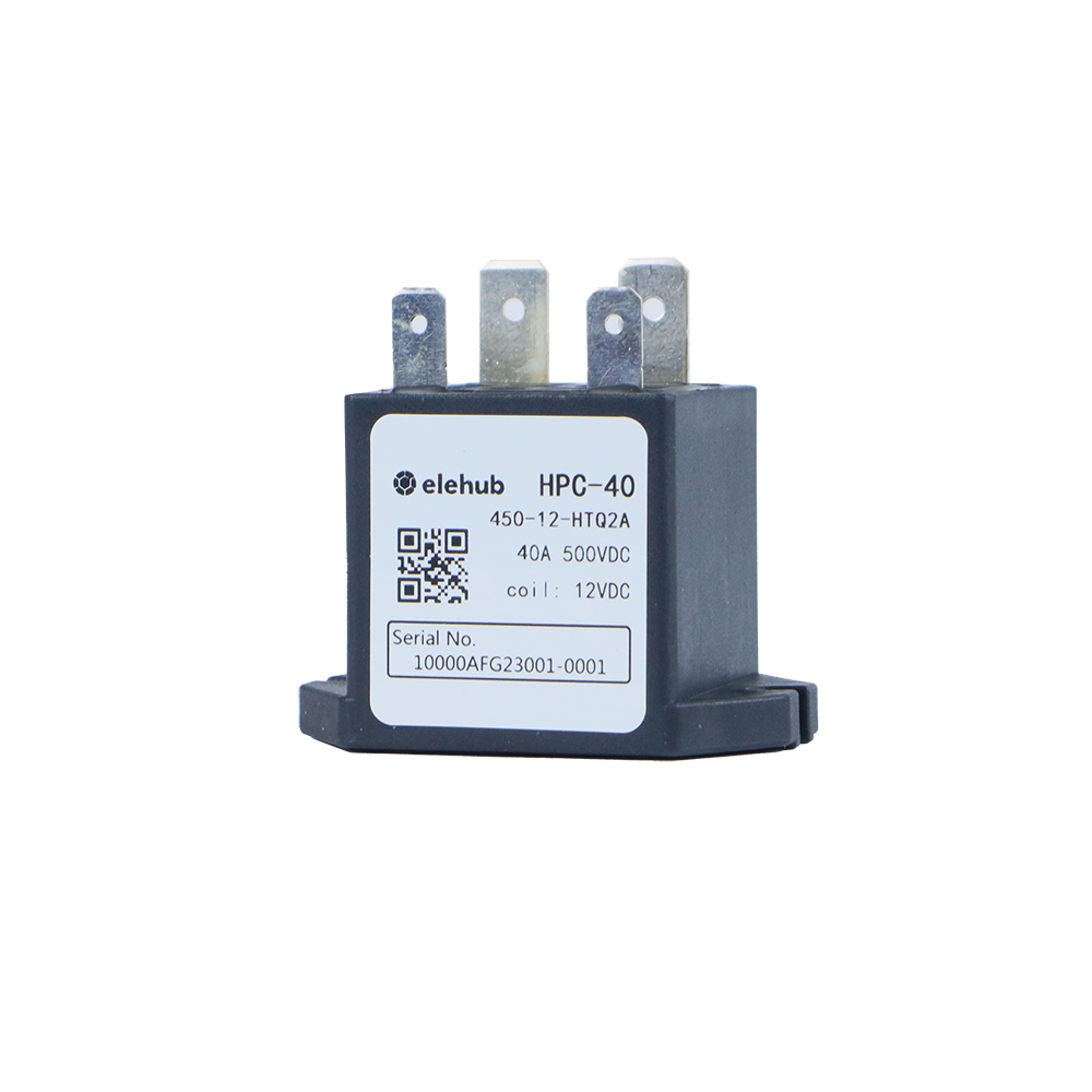
An HVDC contactor is on an SST’s low-voltage DC link, battery port, charging output, auxiliary storage branch, or pre-charge path. Its duties may include energizing a bus, disconnecting a failed module, separating a battery after shutdown, or sidestepping backfeed during service.

Selection must account for more than continuous current:
- Maximum operating and recovery voltage
- Normal, overload, making, and breaking current
- Whether the interruption is polarity-sensitive
- Available fault current and backup fuse coordination
- Coil voltage, economizer behavior, and auxiliary contacts
- Required electrical and mechanical endurance
- Shock, vibration, temperature, altitude, and enclosure conditions
- Pre-charge timing and residual DC-link energy
Mechanical contactors aren’t intended to compete with semiconductors for the first microseconds of a short circuit. A healthy scheme allows the converter to limit current, a fuse or breaker to clear severe faults, and the contactor to provide durable galvanic separation afterward.
That coordination is important. Opening an under-rated device against a stiff DC source can sustain an arc, weld the contacts, or leave the supposedly isolated bus energized.
ELEHUB’s high-voltage DC contactor range entails current ratings from 40 A to 500 A and switching voltages up to 1,500 VDC. It makes the category relevant to energy-storage ports, DC charging buses, and other high-power DC interfaces. The exact model still needs to be matched to breaking duty, polarity, fault coordination, and environmental conditions.
ELEHUB Solutions for Solid-State Transformer Applications
ELEHUB supplies components that can be employed to support protection, sensing, and disconnection on the low-voltage DC ports and auxiliary circuits of an SST.

Complementary product categories include:
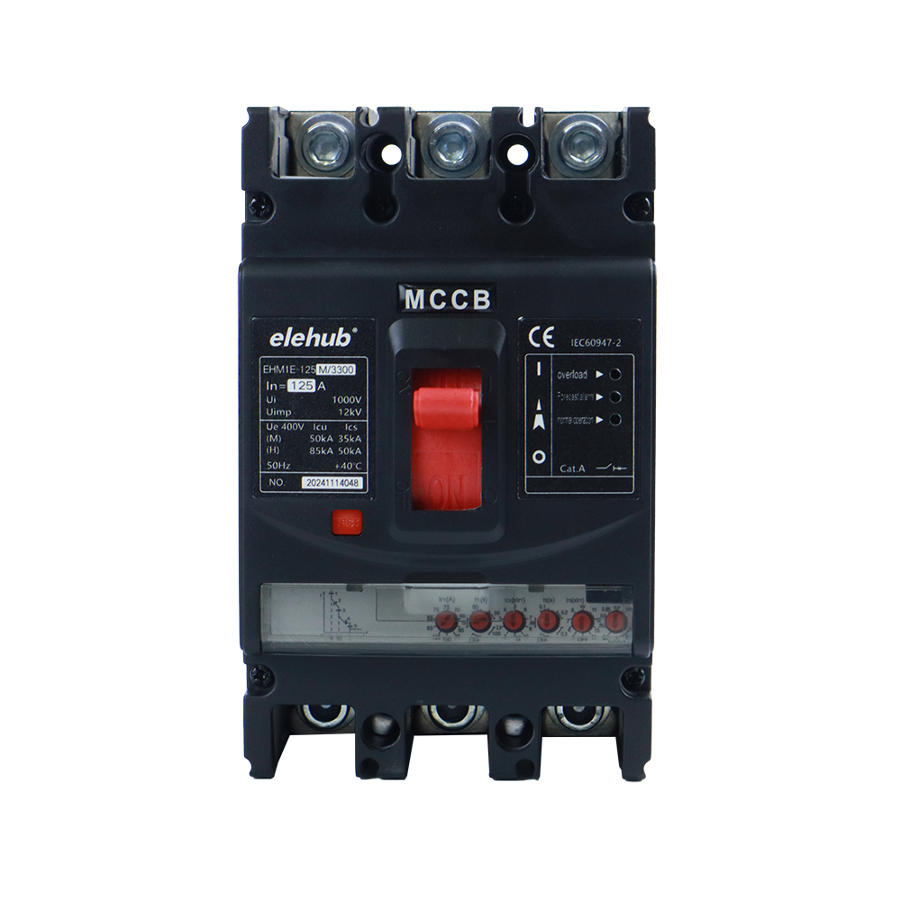
- Circuit breakers: MCB, MCCB, hydraulic-magnetic breakers, and air-circuit-breaker options for protection against overload and short circuits.
- DC fuses: A one-time interruption for high-energy faults that need rapid current clearance and DC arc control will be implemented.
- DC shunts: Low-resistance current measurement for bus monitoring, energy control, and protection feedback. We have many 50-500 A, 50 or 75 mV configurations.
- DC surge protection devices: In order to suppress transient overvoltage, there are product alternatives available for 600, 1,000, and 1,500 VDC systems.
- DC isolator switches: Manual disconnection products are available up to 1,500 VDC for the purpose of service isolation in appropriate DC circuits.
In most cases, these ratings are relevant to low-voltage DC sections. On the other hand, medium-voltage SST input cells demand purpose-engineered insulation, switching, and protection hardware instead of an automatic extension of LVDC catalog components.
Future Trends in Solid-State Transformer Technology
Progress is moving along several tracks, such as:
- Higher-voltage SiC devices
- Soft-switching topologies
- Reduced DC-link capacitance
- Advanced nanocrystalline magnetics
- Improved partial-discharge-resistant insulation
- Modular redundancy
- Grid-forming control
If we talk about commercial development, it is also edging beyond laboratory prototypes. DOE announced funding for a 1 MVA, three-winding full-scale SST that is intended for deployment at a utility-owned substation. Meanwhile, a February 2026 project notice describes about an advanced full-scale AC SST demonstration for a water-pumping application.
The likely path won’t be an overnight sweep that replaces every conventional transformer. Full SSTs should first gain ground where their compactness and control functions solve expensive system problems. Hybrid transformers might cover the middle territory. They can add electronic regulation without having to force all rated power through the converter.
Conclusion
So, what is a solid-state transformer in practical terms? It refers to a power-conversion platform that is digitally controlled as well as that incorporates voltage transformation, isolation, switching, sensing, and power management all inside a single system.
Its future depends less on whether engineers can make one work – they already can – and more on whether manufacturers can deliver the needed efficiency, lifetime, insulation integrity, serviceability, and cost at scale. In data centers, fast chargers, renewable hubs, transport systems, and active microgrids, that equation seems to be plausible. The ordinary distribution transformer isn’t disappearing, but it may soon have a far more capable electronic colleague.
FAQs
Is a solid-state transformer more efficient than a conventional transformer?
Not necessarily. Conventional transformers can achieve excellent efficiency, while SSTs introduce semiconductor losses. Their main advantage is combining power conversion, regulation, isolation, and control.
Can a solid-state transformer replace a conventional transformer?
In some applications, yes, but not universally. Conventional transformers remain preferable for simple voltage transformation, while SSTs offer greater value where active control and DC integration are required.
Can an SST provide backup power during a grid outage?
Yes, when combined with batteries or another energy source. With suitable grid-forming controls, an SST can help maintain a local AC or DC bus during outages.
Are solid-state transformers suitable for EV charging stations?
Yes. SSTs can connect medium-voltage utility power directly to controlled DC charging buses, while coordinating high-power chargers, stationary batteries, and other distributed energy resources.
Can an SST replace a UPS in a data center?
Not by itself. An SST can integrate power conversion and battery systems, but a complete UPS architecture still requires energy storage, bypass functions, redundancy, protection, and control.
Does an SST eliminate the need for fuses, breakers, and contactors?
No. Semiconductor protection reacts quickly, but physical protection devices remain necessary for fault isolation, maintenance disconnection, backup protection, and safe separation of energized DC circuits.
What should engineers consider when selecting a solid-state transformer?
Key factors include voltage, power rating, AC/DC ports, efficiency, isolation, cooling, fault conditions, redundancy, grid requirements, cybersecurity, maintenance strategy, service life, and total cost of ownership.
Will solid-state transformers replace conventional transformers?
Probably not completely. Conventional transformers remain highly effective for basic voltage conversion, while SSTs are more likely to grow in data centers, EV charging, renewable energy, storage, and active distribution networks.