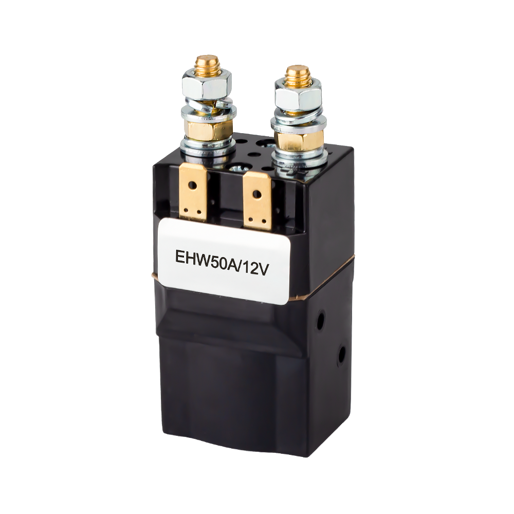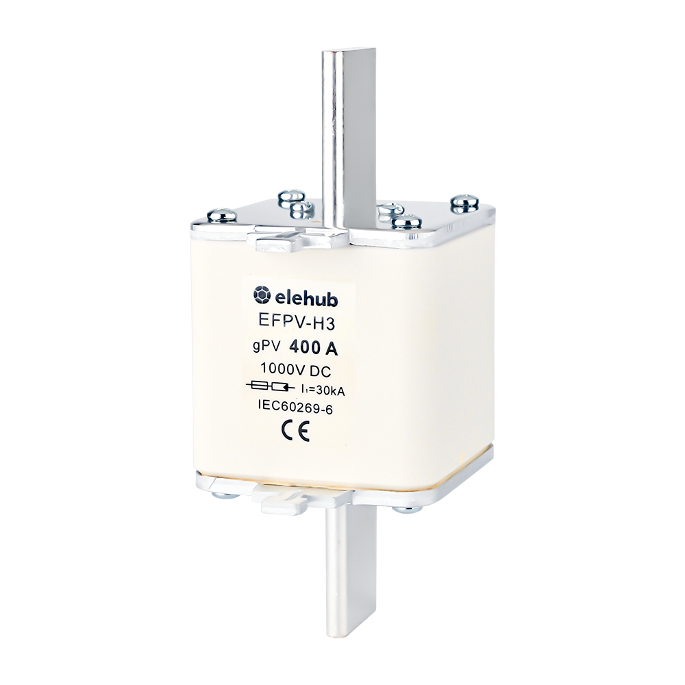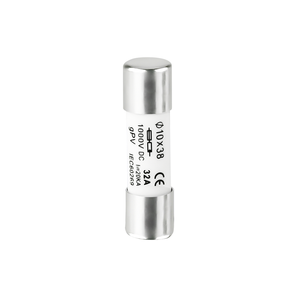
Telecom DC power systems provide stable and continuous power for operating telecommunications equipment. Their primary function is to convert AC power into DC power while ensuring uninterrupted operation. Reliable power delivery is critical, especially for modern 5G networks that require high efficiency and continuous availability.
These systems are designed to maintain communication services without interruption, even during utility power failures. Backup and protection mechanisms make DC power systems highly reliable for telecom applications.
In this post, we will discuss how DC power systems for telecommunications work, including 48V DC architecture, rectifiers, battery backup, and protection systems. Explore why DC power is essential for 5G networks, how power is distributed, and key components ensuring uninterrupted telecom operations.

What Is a Telecom DC Power System?
A DC telecom power system is an integrated power infrastructure that converts AC power from the utility grid into stable DC power for telecom equipment such as base stations, routers, switches, and transmission systems.
Its main purpose is to:
- Provide stable DC power (typically -48V)
- Ensure uninterrupted operation of telecom networks
- Support backup power through battery systems
- Protect equipment from electrical faults and surges
Why DC Power is Preferred in Telecommunications
Telecom equipment primarily operates on DC power. Most telecommunications devices, including switches, routers, BTS systems, and communication controllers, are designed to operate on DC voltage. Centralized DC distribution also reduces the need for separate AC-to-DC converters for individual devices.
- High Reliability: DC in telecom provides stable power without the synchronization and frequency issues associated with AC systems. Fewer power conversion stages reduce the chances of failure and improve overall system uptime.
- Faster Backup Transition: Battery systems store energy directly in DC form. During utility power failure, batteries instantly supply power to the DC bus without switching delays or inverter startup time.
- Low Conversion Losses: Centralized rectifiers convert AC power into DC and distribute it efficiently throughout telecom facilities, reducing overall energy losses and improving system efficiency.
- Stable Voltage for Sensitive Devices: Telecommunication equipment requires highly stable voltage for accurate signal processing and continuous operation. DC systems provide a regulated and stable power supply for sensitive telecom devices.
- Low Electromagnetic Interference (EMI): DC power systems for telecommunications generate less electrical noise than AC systems, resulting in improved signal quality and more reliable communications.
- Simplified Battery Connection: Batteries are directly connected to the DC bus, making backup energy storage simpler, faster, and more reliable.
Standardization of 48V DC Power Supply in Telecom
Modern telecommunications power systems typically use −48V DC architecture, because they provide an effective balance between safety, efficiency, and long-distance power distribution. Today, most telecom infrastructure, including switching stations, mobile towers, data transmission systems, and networking equipment, operates using the standardized 48V DC architecture.
Why Use 48 Volt DC Power in Telecom?
Telecommunication equipment requires continuous and stable power to operate sensitive electronic systems. There are several engineering advantages:
- Safe working conditions for technicians with reduced shock risk
- Efficient and stable power delivery
- Reduced transmission losses over distribution lines
- Balanced performance between efficiency and cable size requirements
- Strong compatibility between legacy and modern equipment
- Reliable integration with telecom battery backup systems
- Reduced corrosion in power systems through negative grounding
This voltage level is now widely adopted across the global telecom industry as a standard operating architecture.

Core Architecture of a DC Telecom Power System
A telecom DC power system consists of multiple interconnected subsystems working together to ensure continuous power delivery.

A Simplified Diagram of a Typical Telecommunications DC Power System
1. AC Power Input (Utility Supply Stage)
The process starts when electrical power from the utility grid enters the telecom facility. Utility supplies typically provide AC voltage levels such as:
- 230V AC
- 400V AC
- 415V AC
- 480V AC
Before being utilized by telecom equipment, this AC power passes through protective and distribution stages to ensure safe and stable operation of downstream systems. It ultimately provides the foundation for AC-to-DC conversion within rectifier units, enabling continuous DC power delivery to critical telecom loads.
2. AC Distribution System (Power Distribution)
AC distribution panels distribute incoming electrical power to different subsystems within the telecom facility.
Their main functions include:
- Power isolation
- Load distribution
- Fault protection
- Maintenance switching
- Generator integration
The AC distribution system supplies power to:
- Rectifier systems
- Cooling systems
- Lighting
- Air conditioning units
- Backup generator controls
The telecom rectifier system is one of the most critical loads because it supplies power to the telecom DC network.
3. Rectifier System (AC to DC Conversion)
Telecom equipment operates on DC power, so the incoming AC supply must be converted into a regulated DC voltage. This function is performed by rectifier systems, which serve as the core energy conversion units within telecom power infrastructure.
Key functions include:
- Converts AC power into a stable −48V DC output
- Voltage regulation under load variation
- Battery charging during normal operation
- Load sharing across multiple modules
SMPS Technology Advantages:
Modern telecom rectifiers commonly use high-frequency switch-mode power supply (SMPS) technology because it offers several advantages, including:
- High energy efficiency
- Compact and space-saving design
- Fast dynamic voltage regulation
- Low heat dissipation
- Modular and scalable architecture for flexible system expansion
Redundancy Design:
Modern telecom rectifier systems commonly adopt modular redundancy architectures such as N+1 or N+N configurations to improve system reliability and fault tolerance.
In an N+1 system, one additional rectifier module operates as a backup unit, allowing continuous operation even if one module fails.
Larger telecom facilities and data centers may use N+N redundancy architectures, where two fully independent power paths are each capable of supporting the entire critical load independently.
4. DC Power Distribution (Load Allocation)
Power distribution delivers a stable DC supply to telecom equipment and subsystems that require continuous and reliable operation.
After conversion, the regulated −48V DC output is supplied to the DC bus. The DC bus acts as the central distribution point for telecom loads. Power is then distributed through DC distribution units (PDUs) to various telecom devices and subsystems.
In high-availability telecom facilities, dual-feed DC bus architectures are often implemented to improve system redundancy and operational continuity. Independent power distribution paths allow critical telecom loads to continue operating even if one power path experiences a failure or requires maintenance.
Each outgoing branch circuit is independently protected to ensure system safety and operational continuity. Typical protection components include DC circuit breakers, fuses, and surge protection devices (SPDs).
5. Load Equipment (Telecom Consumption)
Load equipment represents the final consumption layer in a telecom DC power system, where electrical energy is converted into communication services. These devices rely on a stable −48V DC supply from the DC bus to ensure continuous and reliable operation.
Typical telecom load equipment includes:
- Base Transceiver Stations (BTS)
- Routers
- Network switches
- Fiber-optic transmission systems
- DC-powered servers
- Edge computing units
- Communication controllers
These devices are highly sensitive to voltage fluctuations and require stable, low-noise DC power for accurate signal processing and uninterrupted data transmission. Any instability in the power supply can directly impact network performance, latency, and service availability.
6. Battery Bank (Energy Storage Backup)
Battery banks are directly connected to the DC bus through battery connectors and remain permanently in parallel with the rectifier output, serving as instantaneous backup power.
Operating modes:
- Normal Operating Condition: Rectifiers supply power to telecom loads and simultaneously charge the batteries
- Utility Power Failure: Batteries instantly support the load with virtually no interruption to telecom equipment operation.
These seamless transitions are one of the key advantages of telecom DC power systems.
Battery backup duration depends on several factors, including:
- Battery capacity
- Site load demand
- Required autonomy time
The most commonly used telecom battery technologies include:
- VRLA (Valve-Regulated Lead-Acid) batteries: Widely used due to their mature technology and cost-effectiveness
- Lithium-ion batteries: Offer longer service life, higher energy density, and reduced maintenance requirements
- Nickel-cadmium batteries: Perform reliably under extreme temperature conditions and harsh environments
7. Generator (Backup Support)
If power outages last longer than the battery autonomy time, backup generators provide additional energy support.
The operating sequence is as follows:
- A utility power failure occurs.
- Batteries instantly support the telecom load.
- The generator starts operating automatically.
- The generator supplies AC power to the rectifiers.
- The rectifiers power telecom equipment and recharge the batteries.
To further improve power system availability, telecom sites often integrate redundant generator systems and automatic transfer mechanisms to ensure continuous operation during extended utility outages or equipment failures.
8. Monitoring and Control System
Modern telecom power systems include intelligent monitoring controllers that manage the entire energy flow process.
The monitoring system tracks:
- AC input voltage
- Rectifier performance
- Battery health
- Load current
- Temperature
- Alarm conditions
- Fuel levels
- Power efficiency
To improve reliability and reduce operational workload, modern systems support remote monitoring, allowing network operation centers (NOCs) to manage multiple telecom sites from centralized platforms. This significantly improves response speed and system visibility across distributed infrastructure.
Advanced telecom power systems also integrate IoT sensors, cloud-based monitoring platforms, predictive analytics, and AI-based diagnostics. These technologies enable early fault detection, performance optimization, and predictive maintenance, reducing downtime and maintenance costs.
Battery management systems (BMS) are an important part of this process. They help perform testing, detect faults, and support corrective actions to maintain system stability.
DC shunts are used for accurate current measurement in battery strings and DC distribution lines, enabling real-time monitoring of charge/discharge current and supporting BMS calculations such as state of charge (SOC) and load balancing.

9. Cooling and Thermal System
Telecom power rooms require proper cooling systems and thermal management because servers, batteries, rectifiers, and communication devices generate continuous heat during operation. High temperatures reduce efficiency, shorten battery life, and may damage components.
For stable operation, air conditioning systems, ventilation systems, cooling fans, and heat exchangers are used in telecom systems to control temperature.
Critical telecom facilities may also implement redundant HVAC systems to maintain thermal stability during cooling equipment failures.
10. Positive Grounding System
Most DC telecom systems adopt a −48V DC positive grounded configuration. A typical telecom positive grounding system is defined as follows:
- Positive terminal (+): Connected to earth ground
- Negative terminal (−): Active DC output (−48V)
- Return path: Ground-referenced via bonded positive side
This means that all telecom loads operate between −48V (hot) and 0V (ground reference).
Although the system is commonly referred to as “−48V DC,” the designation does not indicate a change in polarity relative to ground; instead, it reflects that the active conductor operates at approximately −48 volts with respect to the grounded reference point.
Early telecom systems initially used negative grounding similar to automotive electrical systems. However, long-distance outdoor cabling exposed to moisture led to electrolytic corrosion, particularly on positive conductors.

Positive Ground Reduces Corrosion of Moist Telcom Wiring
Source: Why Positive Ground in Telcom Power Systems?
By bonding the positive terminal to earth ground, the telecom power system establishes a negative potential on the active conductor relative to ground. This configuration causes metallic conductors to behave as cathodic elements, significantly reducing galvanic corrosion on telecom conductors and outdoor infrastructure.
As a result, the lifespan and reliability of copper conductors, underground cables, and outdoor telecom infrastructure are substantially improved.
How a Telecom DC Power System Works (Energy Flow)
The energy flow in a telecom DC system follows a structured path:
- AC power enters from the utility grid
- AC is distributed to rectifiers
- Rectifiers convert AC to -48V DC
- DC power is supplied to the DC bus
- Telecom equipment consumes DC power
- Batteries charge or discharge as needed
- Generators provide backup during extended outages
In short: AC → Rectifier → DC bus → Load → Battery → Generator
This layered architecture ensures continuous operation under all conditions. Redundant power architecture, modular rectifier design, and backup energy systems work together to eliminate single points of failure and maximize telecom network uptime.
DC Protection and Safety Engineering in Telecommunication Power Supply
DC protection and fault management are critical elements of telecommunication power systems because DC faults generate continuous electrical arcs that are more difficult to interrupt compared to AC faults.
In AC systems, current naturally crosses zero in each cycle, which helps extinguish arcs. In contrast, DC current flows continuously, so telecom systems require specially designed DC protection devices to safely handle fault conditions.
Major Safety Risks
- Electrical Shock: High DC voltage in telecom systems can cause severe electric shock during faults or maintenance activities.
- Arc Flash Hazards: DC systems can generate intense arc flashes during short circuits, which may damage equipment and harm operators.
- Hydrogen Gas from Batteries: During charging, lead-acid battery banks release hydrogen gas, which can lead to explosion risks if ventilation is inadequate.
- Thermal Runaway: Lithium-ion batteries may overheat and enter thermal runaway, causing rapid temperature rise and fire hazards.
- Fire Risks: Battery failures and overheating can lead to fire incidents in telecom power rooms.
- Grounding Failures: Poor grounding increases electric shock risk and reduces the effectiveness of protection systems.
Protection Devices
Protection devices are used in telecom DC power systems to protect different components from overloading, electrical faults, and other fault conditions.
Key protection components include:
- DC Breakers: Isolate faulty sections of the circuit during overcurrent or short-circuit events
- Telecom Fuses: Provide high-speed overcurrent protection by melting under excessive current flow
- Surge Protection Devices (SPD): SPD in telecom protects systems from voltage spikes caused by lightning by diverting surge energy to ground
- Telecom Disconnect Switches: Safely disconnect circuits during maintenance or emergency shutdowns
- Reverse Polarity Protection: Prevents damage caused by incorrect battery connection
- Ground Fault Detection Systems: Monitor leakage currents and identify insulation or grounding failures. More about ground fault and protection here.
Safety Protection Measures
- Battery Ventilation: Removes hydrogen gas buildup and reduces explosion risks.
- Arc-Resistant Equipment Design: Protects operators and equipment from arc flash energy. Learn more about arc flash protection strategies here.
- Insulated Tools and PPE: Minimize accidental short-circuit risks during maintenance work.
- Lockout/Tagout (LOTO) Process: Ensures systems are fully de-energized before servicing.
- Thermal Monitoring: Continuous monitoring of the battery and system temperature helps detect overheating at an early stage.
Preventative Maintenance and Lifecycle Management
Telecom DC systems require ongoing maintenance to ensure long-term reliability:
- Routine inspection of rectifiers and batteries
- Predictive maintenance using digital monitoring tools
- Scheduled battery replacement cycles
- Environmental condition tracking (temperature, humidity)
- Performance degradation analysis over time
Lifecycle management reduces unexpected failures and optimizes total cost of ownership.
Why Higher DC Voltage Improves Power Efficiency in Telecom Systems
The telecom system also distributes power over larger system rooms, outdoor cabinets, or towers. Therefore, using higher DC voltages improves transmission efficiency because current decreases when voltage increases for the same power level.
This relationship is shown as:
P = VI
Where:
- P = power
- V = voltage
- I = current
For a fixed power requirement, increasing voltage reduces the current needed.
Reduced Cable Losses and Heat Generation
Electrical cables generate heat due to conductor resistance. Power losses in conductors are expressed as:
Ploss = I²R
Since losses increase with the square of the current, reducing the current significantly lowers cable heating.
Lower cable losses improve:
- Energy efficiency
- Thermal performance
- System reliability
- Cable lifespan
Improved Voltage Stability Over Long Distances
A long cable experiences higher voltage losses. By reducing the current level, a −48 VDC system minimizes conductor voltage drops, helping telecom components receive a stable operating voltage even over longer distances.
Stable voltage is required for:
- Signal processing
- RF transmission systems
- Data communication
- Sensitive electronics
Reduced Conductor Size and Material Cost
Lower current also reduces the required conductor size. This provides benefits in telecom systems, such as:
- Smaller cables
- Lower copper usage
- Compact cable management systems
Advantages include:
- Lower installation cost
- Easier infrastructure routing
- Reduced cable weight
- High scalability
Efficiency Evolution: From -48V to High Voltage DC (HVDC)
Traditionally, -48V DC has been the “golden standard” for telecom due to its safety and corrosion resistance. However, as 5G power demands increase (often 3x higher than 4G), the industry is moving toward higher voltages to overcome the physical limits of copper cabling.
The industry is currently following a three-tier roadmap:
| Voltage Level | System Role | Key Characteristics |
| Standard -48V DC | Legacy telecom baseline | Highly safe, widely standardized, ideal for traditional indoor equipment |
| Boosted -57V DC | 5G upgrade layer |
Compensates for voltage drop and improves efficiency without replacing legacy systems. As defined by ETSI standards, the normal operating voltage range for 48V DC nominal systems is 40.5V to 57V DC. |
| HVDC (240V–400V DC) | Next-generation architecture | High efficiency, reduced losses, ideal for data centers and Cloud-RAN hubs |
Higher voltage systems enable:
- Lower transmission losses
- Reduced cooling requirements
- Improved energy efficiency per site
- Scalable architecture for dense network deployment
But also come with:
- Higher safety risk (arc flash and electric shock potential increases)
- More complex protection and insulation requirements
- Stricter system design for clearances and grounding
- Higher initial deployment and upgrade costs
- Compatibility challenges with legacy -48V telecom infrastructure
- More advanced maintenance and skilled operation requirements
Engineers determined that lower DC voltages provide safer operating conditions for technicians, while higher voltages improve transmission efficiency. The future of telecom power systems is not simply about increasing voltage, but about finding the optimal balance between efficiency, safety, and system complexity.
Future Trends in Telecom Power Systems

Telecom DC power systems are evolving rapidly with advancements in:
- 5G network expansion
- AI-based monitoring systems
- Lithium-ion battery adoption
- Renewable energy integration (solar + wind)
- Edge computing infrastructure
- Smart energy management systems
These trends are driving higher efficiency, automation, and sustainability.
Conclusion
Telecom DC power systems form the critical foundation of global communication infrastructure. Their design prioritizes reliability, efficiency, and continuous operation under all conditions.
With standardized 48V DC architecture, advanced rectification technology, battery system, accurate monitoring system, and latest protection device, these systems ensure uninterrupted connectivity in an increasingly digital world.
The telecom system is regularly shifting towards 5G, edge computing, renewable power infrastructure, AI-based monitoring, and telecom DC power systems, which are highly effective, energy efficient, and digitally controlled.
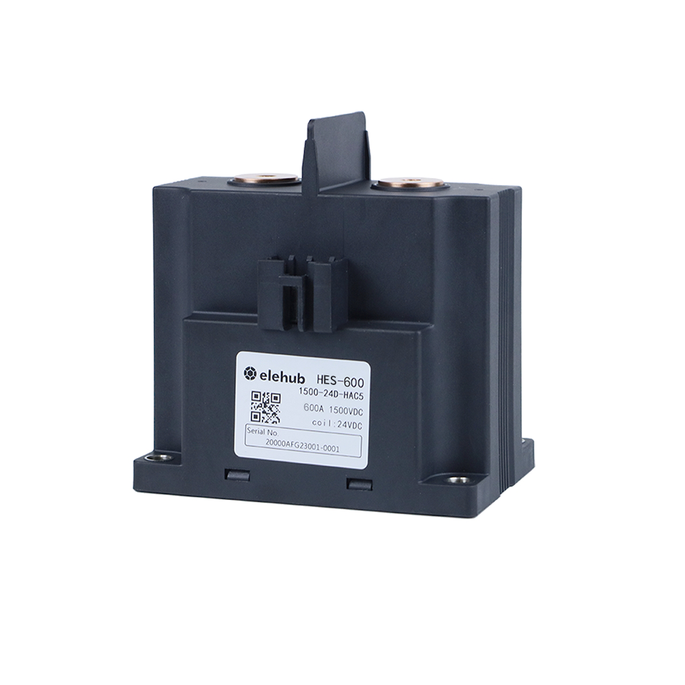
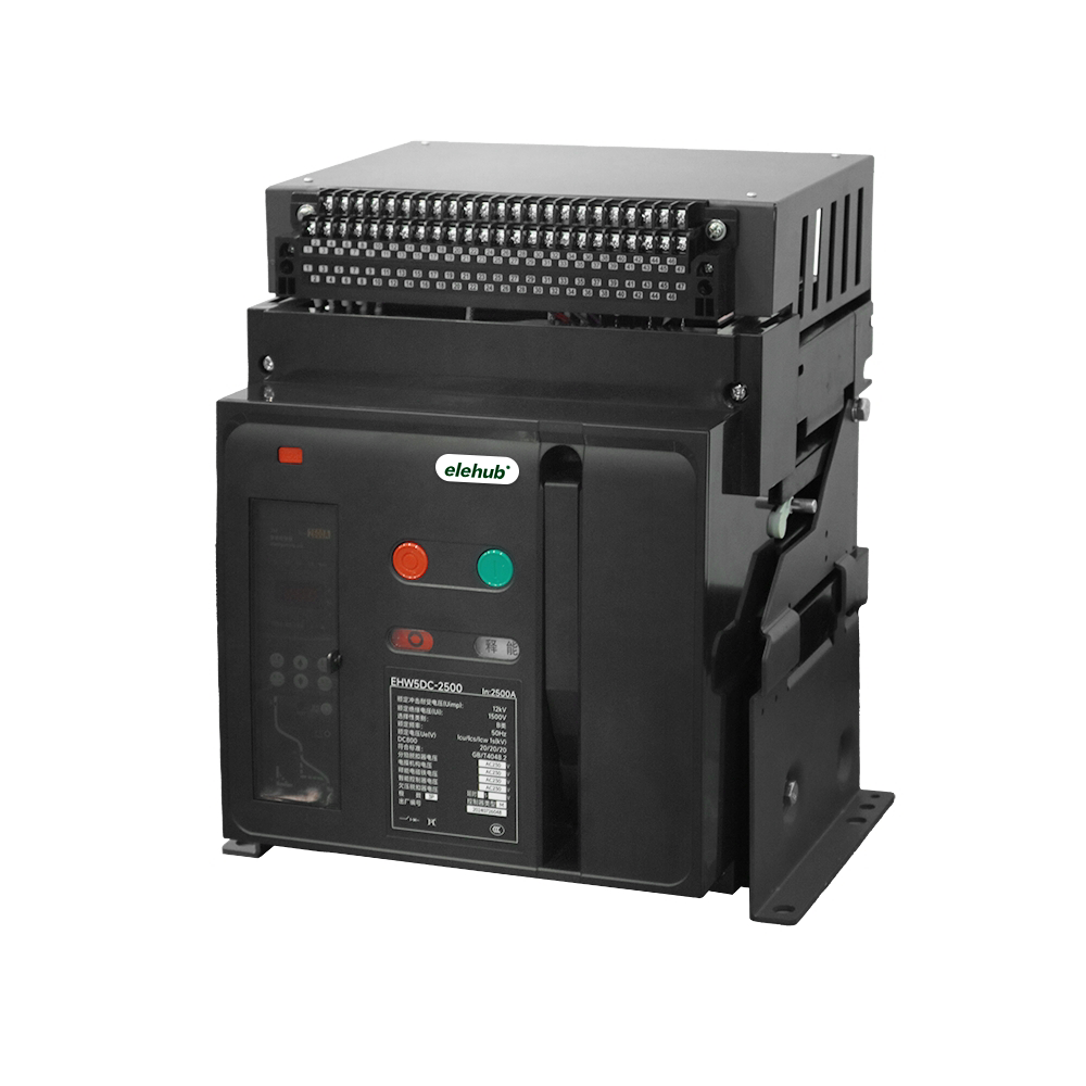
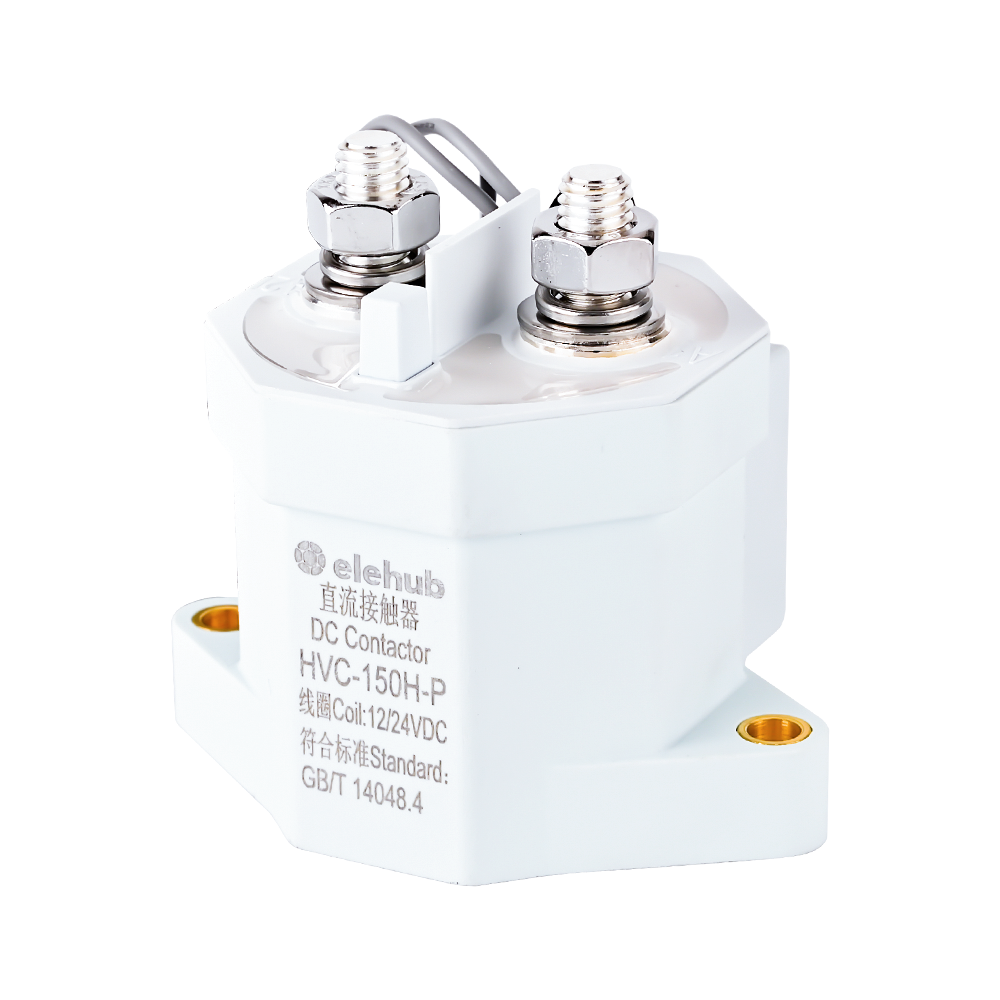
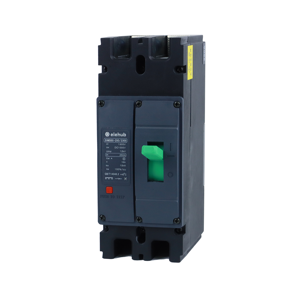
For modern DC applications, ELEHUB provides a range of electrical protection and switching solutions designed to support safe, efficient, and stable DC power distribution across telecom and related energy systems.