Surge Protective Devices (SPDs), also known as surge protectors or lightning arresters, are used to protect electrical and electronic equipment from voltage surges or spikes caused by lightning strikes, switching operations, or electrical faults. Understanding surge protection device types is essential, as SPDs are generally classified into three main types: Type 1, Type 2, and Type 3, each designed for specific applications and installation points within an electrical power system.
In this tutorial, we will explore the detailed features of surge protective devices and compare the different types to define their characteristics and applications clearly. Let’s get started.

Why Surge Protection Is Critical in Modern Power Systems
Modern electrical power systems rely heavily on sensitive electronic components, automation systems, digital controls, renewable energy sources, and interconnected networks. While these technologies improve efficiency and reliability, they also increase vulnerability to voltage surges and transient overvoltages.

Voltage surges are short-duration increases in electrical voltage that can occur due to lightning strikes, utility grid switching operations, capacitor bank switching, motor start-ups, power outages, or faults within the electrical network. Even surges lasting only microseconds can damage insulation, degrade electronic components, corrupt data, or cause immediate failure of equipment.
In today’s environments—such as industrial plants, commercial buildings, data centers, hospitals, and solar PV installations—the cost of downtime and equipment damage is extremely high.
A single surge event can lead to:
- Failure of PLCs, servers, and control systems
- Damage to inverters, drives, and power supplies
- Increased maintenance costs and unplanned shutdowns
- Reduced equipment lifespan and safety risks
Because traditional protective devices like fuses and circuit breakers respond too slowly to transient overvoltages, they cannot provide effective surge protection. This makes surge protective devices (SPDs) a critical part of modern electrical system design.
Surge protection is no longer optional—it is a fundamental requirement for system reliability, safety, and compliance with international electrical standards.
Introduction to Surge Protection Devices (SPDs)
A surge protective device (SPD) ensures the safe operation of an electrical power system by protecting it from sudden voltage changes or surges. These surges can result from lightning strikes, power outages, or switching operations such as turning machines on and off.
SPDs divert excess voltage away from sensitive equipment, protecting devices from damage caused by sudden voltage fluctuations.
SPDs are available in different designs and configurations, each intended for specific applications. Some SPDs are installed at the building level to provide overall system protection, while others are designed to protect individual devices or specific equipment.
Components of Surge Protection Devices
Surge protective devices consist of different components, each performing a specific function. Some of the main components are:
1. Voltage-Limiting Elements
These are the heart of the SPD. They clamp excessive voltage to a safe level. There are three core component technologies:
- Metal Oxide Varistors (MOVs): These are ceramic-based components whose resistance depends on the applied voltage. When the voltage increases beyond a certain level, their resistance decreases, allowing them to divert excess voltage away from protected equipment.

By Stefan Riepl (Quark48) – Self-photographed, Public Domain
https://commons.wikimedia.org/w/index.php?curid=12444899
-
Gas Discharge Tube (GDT): A gas discharge tube contains electrodes sealed in an inert gas that ionizes when a high voltage surge occurs, creating a low-resistance path to ground. It can handle very high surge currents but has a slower response time compared to solid-state devices.

By Ulfbastel – Own work, Public Domain
https://commons.wikimedia.org/w/index.php?curid=2768406
-
Transient Voltage Suppression (TVS) Diodes: TVS diodes are semiconductor devices that respond extremely quickly to voltage spikes by clamping the voltage to a safe level. They are ideal for protecting sensitive electronic circuits but have lower energy-handling capability than MOVs or GDTs.

By Movzx – Own work, Public Domain
https://commons.wikimedia.org/w/index.php?curid=1721753
| Feature | MOV (Metal Oxide Varistor) | GDT (Gas Discharge Tube) | TVS (Transient Voltage Suppressor) |
| Operating Principle | Voltage-dependent nonlinear resistor | Gas ionization and arc discharge | Avalanche breakdown (Zener effect) |
| Typical Response Time | Fast (10–50 ns) | Slow (100 ns–µs) | Very fast (<1 ns) |
| Clamping Voltage Accuracy | Moderate | Poor (high overshoot) | Very good (tight clamping) |
| Surge Current Capability | High (kA range) | Very high (tens of kA) | Low to moderate |
| Energy Handling | High | Very high | Low |
| Leakage Current | Moderate | Very low | Low |
| Lifespan | Moderate, ages over time | Moderate, may fail after an extreme surge | High, no degradation within ratings |
| Follow Current Risk | No | Yes (may need series impedance) | No |
| Typical Voltage Range | 18 V – several kV | 75 V – several kV | 5 V – ~600 V |
| Size | Small to medium | Medium | Small |
| Cost | Low | Medium | Low to medium |
| Best Use Case | AC mains, power distribution | Lightning & telecom lines | Signal lines, low-voltage electronics |
2. Disconnection / Protection Mechanism
Prevents fire or damage if the SPD element fails:
- Thermal Disconnect: A thermal disconnect separates the voltage-limiting element from the circuit when excessive heat is detected, preventing overheating and fire in the event of component failure.
- Fuses or Circuit Breakers: Fuses or circuit breakers protect the MOVs and the overall SPD from excessive current surges. If the current exceeds a safe limit, the fuse disconnects the circuit to prevent further damage.
- Short-Circuit Protection: Short-circuit protection ensures the SPD fails safely by clearing fault currents rapidly, preventing sustained short circuits and damage to the electrical system.
3. Status Indicator
Status indicators show the operational status of the surge protective device. They can be a mechanical flag (green/red), an LED light, or remote signaling contacts for industrial monitoring, helping users identify whether the SPD is functioning properly or needs replacement.

4. Enclosure / Housing
Protects internal components from environmental effects and ensures electrical and fire safety.
5. Connection Terminals
Provide low-impedance electrical connections to line, neutral, and earth for effective surge diversion.
6. Grounding Path
Offers a safe route for surge current to flow into the earth, which is essential for SPD performance.
How Surge Protective Devices Work
The working principle of surge protective devices is simple. When a voltage surge travels through the power lines, the MOVs (Metal Oxide Varistors) reduce their resistance and become highly conductive. This allows them to divert most of the excess current safely to the ground.

As a result, the surge current is redirected and reduced to a less harmful level before it can damage electrical devices with high voltage.
Some Terms for SPD’s Operations
| Feature | Details |
| Un | Nominal system voltage. This is the rated voltage of the SPD under normal operating conditions. |
| Uc | Maximum continuous operating voltage. This defines the highest voltage the SPD terminals can safely face during normal operation. Exceeding this voltage may damage the SPD. |
| Up | Voltage protection level. The maximum voltage the SPD allows to pass through to the protected equipment during a surge. It indicates how effectively the SPD clamps transient overvoltages. |
| Iimp | Impulse current rating. The maximum current the SPD can handle from a high-energy surge such as a direct lightning strike, tested using a 10/350 µs waveform. |
| In | Nominal discharge current. The SPD’s rated surge current that it can carry repeatedly without damage, usually tested with an 8/20 µs waveform. |
| Imax | Maximum discharge current. The highest surge current the SPD can withstand for a short pulse (8/20 µs waveform) before failure. |
| Isccr | Short-circuit withstand capacity. The maximum RMS current the SPD can safely endure in case of a short circuit without catastrophic failure. |
Surge Protection Device Types and Classification
Surge Protective Devices (SPDs) are classified based on their location in the electrical system, their surge-handling capability, and the type of surge waveform they are designed to withstand. International standards such as IEC 61643-11 and UL 1449 define three primary SPD categories: Type 1, Type 2, and Type 3.
Each SPD type plays a specific role in a coordinated surge protection system:
- Type 1 SPDs are designed to handle high-energy surges caused by direct lightning strikes and are installed at the service entrance or main incoming supply.
- Type 2 SPDs protect against induced lightning surges and switching transients and are installed at distribution and sub-distribution panels.
- Type 3 SPDs provide fine protection for sensitive equipment and are installed close to the load or point of use.
This layered or “cascaded” protection approach ensures that surge energy is progressively reduced as it moves through the electrical system, preventing damage to downstream equipment.
For practical identification, many SPDs are marked with T1, T2, or T3, corresponding to their type, making selection and coordination easier for installers and system designers.

Understanding SPD classification is essential for selecting the correct device, ensuring proper coordination between protection levels, and achieving effective long-term surge protection. The following sections explain each SPD type in detail, including their working principles, technical features, installation practices, and applications.
Type 1 SPD (Lightning Current Arrester)
Type 1 SPD is the first level of protection in a surge protection system. It is designed to handle high-energy surges, such as those caused by direct lightning strikes or power grid faults.
These devices are typically installed at the main service entrance, where power enters the building from the utility, and in areas prone to thunderstorms or with exposed conductors, such as overhead power lines. Typical installation locations include main boards, transformer panels, service entrances, and incoming lines.
Type 1 SPDs are capable of handling high current impulses with a 10/350 microsecond waveform, which is the standard test waveform used to simulate lightning strikes.
If a Type 1 SPD is not installed, a direct lightning strike can cause a powerful surge to travel through the electrical system, potentially damaging connected equipment and compromising the entire installation.
Technical Features
- Nominal System Voltage (Un): 230 / 400 V AC (single-phase / three-phase)
- Maximum Continuous Operating Voltage (Uc): 255 V AC (L–N), 440–480 V AC (L–L)
- Lightning Impulse Current (Iimp): Commonly at 12.5kA, 15kA, 20kA, 25kA, up to 100kA (10/350 µs waveform)
- Nominal Discharge Current (In): 20 kA (8/20 µs waveform)
- Maximum Discharge Current (Imax): 50 kA (8/20 µs waveform)
- Voltage Protection Level (Up): ≤ 2.5 kV (typical range: 2.0–4.0 kV)
- Response Time: ≤ 100 ns
- Short-Circuit Withstand Capacity (Isccr): 25 kA rms (some models up to 50 kA)
- Number of Poles: 1P, 2P, 3P, 3P+N, or 4P (depending on system)
Advantages
- Withstands direct lightning currents
- Protects the entire installation
- Essential for buildings with external lightning protection systems
Limitations
- Higher residual voltage
- Not suitable for protecting sensitive electronics alone
- Higher cost
Type 2 SPD (Surge Arrester)
Type 2 SPDs are installed downstream of Type 1 SPDs, typically at distribution panels, subpanels, or branch circuits within a facility. These devices manage indirect lightning surges and residual surge energy that passes through the Type 1 SPD, as well as internally generated surges, such as those caused by motor starting or switching operations.
Type 2 SPDs are tested using an 8/20 microsecond waveform, which represents lower-energy surges with faster transients compared to direct lightning strikes. By limiting the voltage to a safe level, these devices protect equipment connected to the distribution panel from damage.
Type 2 SPDs employ protection techniques such as metal oxide varistors (MOVs), gas discharge tubes (GDTs), or hybrid combinations of both. MOV-based designs provide fast response times and effective voltage clamping, while GDTs offer high surge current handling capability. Hybrid designs combine the advantages of both technologies to achieve improved performance and durability.
In industrial applications, Type 2 SPDs are used to protect machinery, control panels, servers, and electrical rooms located away from the main service entrance. In residential settings, they safeguard appliances and devices connected to secondary panels.
Type 2 SPDs are typically used in coordination with Type 1 SPDs to create a comprehensive and effective surge protection system.
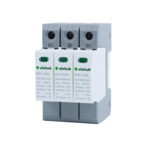
Technical Features
- Nominal System Voltage (Un): 230 / 400 V AC
- Maximum Continuous Operating Voltage (Uc): 275 V AC (L–N), 440–480 V AC (L–L)
- Nominal Discharge Current (In): 20 kA (8/20 µs)
- Maximum Discharge Current (Imax): Commonly at 20kA, 40kA, 60kA, 80kA, 100kA, up to 200kA (8/20 µs)
- Voltage Protection Level (Up): ≤ 1.5 kV
- Response Time: ≤ 25 ns
- Short-Circuit Withstand Capacity (Isccr): 25 kA rms
- Number of Poles: 1P / 2P / 3P / 3P+N / 4P
Advantages
- Good balance between protection level and cost
- Effective for internal surge suppression
- Can be used as standalone protection where Type 1 is not required
Limitations
- Cannot handle direct lightning currents
- Degrades gradually with repeated surges
Type 3 SPD (Fine Protection SPD)
Type 3 SPDs are the final layer of surge protection and are installed close to sensitive equipment. They are commonly integrated into wall outlets, power strips, or directly into devices such as medical equipment, computers, and electronic appliances.

A power strip with built-in surge protector
By SurgeIntern – Own work, CC BY-SA 4.0
https://commons.wikimedia.org/w/index.php?curid=76033381
Their primary function is to handle low-energy transients that pass through upstream Type 1 and Type 2 SPDs or are generated within the local circuit.
Type 3 SPDs are tested using a 1.2/50 microsecond voltage waveform and an 8/20 microsecond current waveform. They typically have a lower surge current capacity, ranging from 3 kA to 10 kA, but provide precise voltage clamping to protect sensitive electronic devices. These devices are designed to limit the voltage to safe levels, often below 600 volts, depending on the application and system requirements.
Type 3 SPDs use protection techniques such as metal oxide varistors (MOVs), transient voltage suppression (TVS) diodes, or hybrid suppression circuits. MOVs provide effective voltage clamping, TVS diodes offer extremely fast response times for sensitive electronics, and hybrid designs combine both to enhance protection performance and reliability.
Technical Features
- Test Waveform: 8/20 µs (low energy) and 1.2/50 µs voltage wave
- Nominal System Voltage (Un): 230 V AC
- Maximum Continuous Operating Voltage (Uc): 255 V AC
- Nominal Discharge Current (In): Less than Type 1/2, commonly ≤ 5 kA (8/20 µs)
- Maximum Discharge Current (Imax): 5 kA (8/20 µs)
- Voltage Protection Level (Up): Very low (often ≤ 1.5 kV) to protect sensitive electronics
- Response Time: ≤ 1 ns
- Short-Circuit Withstand Capacity (Isccr): 6 kA rms
- Number of Poles: 1P / 2P
Advantages
- Provides precise voltage clamping for sensitive electronics
- Fast response time protects against rapid transients
- Compact design allows installation directly at outlets or devices
- Hybrid technology combines MOVs and TVS diodes for enhanced reliability
- Complements upstream Type 1 and Type 2 SPDs in a cascaded protection system
Limitations
- Low surge current handling compared to Type 1/2 SPDs
- Cannot replace upstream SPDs for high-energy surges
- Typically designed for AC systems, specific DC or industrial voltages may require special models
Differences Between Type 1, Type 2, and Type 3 SPD
The following table summarizes the key features, functions, and applications of T1, T2, and T3 SPDs:
|
Features
|
Type 1 SPD
|
Type 2 SPD
|
Type 3 SPD
|
|
Function
|
Diverts direct lightning currents
|
Limits induced and switching surges
|
Clamps residual overvoltages
|
|
Installation Location
|
Main service entrance / upstream of the building’s electrical system
|
Distribution panels, subpanels, branch circuits downstream of Type 1
|
Close to sensitive equipment, integrated into outlets, power strips, or devices
|
|
Test Waveform
|
10/350 µs
|
8/20 µs
|
8/20 µs (low energy) & 1.2/50 µs voltage wave
|
|
Impulse Current (Iimp)
|
High (Up to 100 kA)
|
Not applicable
|
Not applicable
|
|
Nominal Discharge Current (In)
|
12.5–20 kA
|
5–20 kA
|
Typically ≤ 5 kA
|
|
Maximum Discharge Current (Imax)
|
25–50 kA
|
20 to 40 kA or higher, up to 200 kA
|
3–10 kA
|
|
Voltage Protection Level (Up)
|
Highest among the three (≈2.5–4 kV)
|
Medium (≈1.5–2 kV)
|
Lowest (often ≤ 1.5 kV)
|
|
Energy Handling Capacity
|
Very high
|
Medium
|
Low
|
|
Protection Distance
|
Protects the complete installation
|
Protects downstream circuits
|
Protects individual devices
|
|
Internal Components
|
Spark gaps, hybrid arresters, GDTs
|
MOVs, GDTs, hybrid
|
MOVs, TVS diodes
|
|
Response Time
|
≤ 100 ns
|
≤ 25 ns
|
≤ 1 ns
|
|
Use as Standalone Protection
|
Yes (at service entrance only)
|
Yes (if no Type 1 required)
|
No (requires upstream SPD)
|
|
Failure Impact
|
Remains conductive briefly during strike
|
Degrades over time
|
Degrades fastest
|
|
Applications
|
Buildings with external lightning protection systems
|
Residential, commercial, industrial panels
|
PLCs, Electronics, IT, and medical devices
|
|
Standards
|
IEC 61643-11
|
IEC 61643-11
|
IEC 61643-11
|
Correlation Between Class I / II / III and Class B / C / D
Surge Protective Devices (SPDs) can be classified using IEC terminology (Class I, II, III) or alternative classifications (Class B, C, D). These systems describe the SPD’s energy handling capability, installation location, and surge waveform.
|
IEC Classification
|
Alternate Classification (B / C / D)
|
Equivalent SPD Type
|
Test Waveform
|
Installation Location
|
Main uses
|
|
Class I
|
Class B
|
Type 1 SPD
|
10/350 µs
|
Service entrance, main incoming panel
|
Discharge direct lightning current
|
|
Class II
|
Class C
|
Type 2 SPD
|
8/20 µs
|
Sub-distribution boards
|
Protection from induced and switching surges
|
|
Class III
|
Class D
|
Type 3 SPD
|
8/20 µs
|
Close to sensitive equipment
|
Fine protection, residual surge clamping
|
Key Point: The Class I/II/III system aligns directly with Type 1/2/3 SPDs, while the B/C/D terminology is an alternate standard mainly used in Europe.
Coordination and Cascaded Protection Strategy
Cascaded surge protection is based on the coordinated use of Type 1, Type 2, and Type 3 SPDs installed at different levels of an electrical system. Each SPD is responsible for handling a specific surge energy level, allowing surge currents and overvoltages to be reduced step by step as they propagate through the system.
Since no single SPD can effectively manage all surge conditions, a layered protection approach is essential for reliable system performance and equipment safety.
Principle of Cascaded Surge Protection
Cascaded protection works on the principle of step-by-step energy dissipation and voltage limitation:
- T1 SPD: Installed at the service entrance, it diverts high-energy lightning currents and prevents direct lightning surges from entering the installation.
- T2 SPD: Installed at distribution or sub-distribution panels, it limits residual surge energy and suppresses internally generated switching overvoltages.
- T3 SPD: Installed close to sensitive equipment, it provides fine protection by clamping low-energy residual surges to very low voltage levels.
Each downstream SPD is exposed to a lower surge energy level, ensuring effective protection and longer service life.
Lightning Protection Zones (LPZ) and SPD Coordination
Surge protection is often designed using the Lightning Protection Zone (LPZ) concept:
| LPZ Zone | Typical Location | SPD Type | Main Function |
| LPZ 0 | Utility supply / exposed area | Type 1 | Discharge direct lightning current |
| LPZ 1 | Main and sub-distribution panels | Type 2 | Suppress induced and switching surges |
| LPZ 2 | Equipment and terminals | Type 3 | Fine protection for sensitive devices |
This zoning ensures controlled voltage reduction at each system boundary.
Key Requirements for Effective Coordination
1. Energy Coordination
Upstream SPDs must have higher surge current ratings, while downstream SPDs handle lower-energy residual surges.
2. Voltage Coordination
The voltage protection level (Up) must decrease downstream:
- Type 1: highest Up
- Type 2: medium Up
- Type 3: lowest Up
This guarantees staged voltage limitations.
3. Distance and Decoupling
- A minimum cable length of 5–10 meters is recommended between Type 2 and Type 3 SPDs
- If distance is insufficient, decoupling inductors should be used
Cable impedance helps limit surge current flow to downstream devices.
4. Grounding Coordination
All SPDs must be bonded to a common low-impedance grounding system. Poor grounding significantly reduces SPD effectiveness and increases residual voltage.
Typical Cascaded Protection Layout
- Service entrance / main incoming panel → Type 1 SPD
- Distribution and sub-distribution panels → Type 2 SPD
- Near sensitive equipment or point-of-use → Type 3 SPD
This structure is widely applied in:
- Industrial facilities
- Commercial buildings
- Data centers
- Hospitals
- Solar PV and renewable energy systems
Why Some SPDs Are Marked with T1/T2 or T2/T3 Simultaneously

1. Combination or Hybrid SPDs
Some SPDs are designed to fulfill the requirements of two SPD types at once, providing both high-energy and fine protection in a single device.
- T1/T2 SPD can handle direct lightning current like Type 1, while also providing switching surge protection like Type 2.
- T2/T3 SPD offers distribution-level protection (Type 2) and equipment-level fine protection (Type 3).
2. Reduced Number of Devices
Using a hybrid SPD reduces the need for separate SPDs at each stage, which can save space, simplify wiring, and reduce installation costs.
Especially useful in compact distribution panels or residential PV systems.
3. Standards Compliance
IEC 61643-11 allows multi-class SPDs, as long as the device meets the impulse current handling (Iimp) and voltage protection level (Up) requirements of both types.
For example, a T1/T2 SPD must safely conduct 10/350 μs lightning currents (Type 1) and 8/20 μs surge currents (Type 2).
4. Application Flexibility
Marking a device as T1/T2 or T2/T3 indicates it can be used at multiple levels in a cascaded system, providing flexibility for designers and installers.
This is particularly helpful in industrial, PV, and EV charging installations, where space or cost constraints make multi-functional SPDs advantageous.
How to Choose the Right Surge Protective Devices
Choosing the right SPD requires careful consideration of site risks, device sensitivity, regulatory standards, budget, and the SPD type. Follow these guidelines to ensure effective protection:
Risk Assessment
Selecting an accurate surge protection device first involves a proper risk assessment, since each site experiences different surge conditions. Follow these points to identify potential risks:
- First, determine whether the area experiences frequent lightning strikes, as such locations require a high level of protection.
- If your location is close to industrial facilities or power stations, surges are more likely to occur, so stronger protection is needed.
- Monitor the voltage and current of the power source, as higher voltage levels can result in higher surge levels.
- Check wire connections carefully, since longer wires can easily transfer surges to connected devices.
- Follow proper electrical standards during installation.
Applied Areas
-
Residential house (underground supply): Install a Type 2 SPD at the main distribution board and Type 3 SPDs at critical sockets to protect appliances from switching surges and residual voltage spikes.
-
Residential house (overhead supply): Use Type 1 + Type 2 SPDs at the main board, with Type 3 SPDs near devices to guard against direct lightning, switching surges, and fine voltage fluctuations.
-
Industrial plant: Deploy Type 1 SPDs at the service entrance, Type 2 SPDs at sub-panels, and Type 3 SPDs at sensitive equipment for layered surge protection across all electrical levels.
-
Data center or hospital: Implement a fully coordinated T1 + T2 + T3 SPD system to ensure maximum protection for critical electronics, servers, and life-support systems from lightning strikes and residual surges.

Sensitive Devices
Each device reacts differently to surges. Medical devices and computers are highly sensitive, while equipment such as lights and heaters can tolerate small surges. Therefore, before selecting a surge protection device, you must consider the sensitivity level of the equipment you want to protect.

Cost Factors
The selection of an appropriate device also depends on the budget. Each type has a specific price: Type 1 SPDs are the most expensive as they protect the entire building, Type 2 SPDs are less costly and protect branch circuits, and Type 3 SPDs cost the least and protect individual devices.
|
SPD Type
|
Typical Cost
|
|
Type 1
|
$150 – $600+
|
|
Type 2
|
$50 – $250
|
|
Type 3
|
$10 – $60
|
How to Install SPDs
T1 SPD Installation
This SPD is installed at the service entrance or transformer panel, usually during new building construction. Follow these points when installing a Type 1 SPD:
- First, turn off the power supply and follow all required safety precautions.
- Install the Type 1 SPD close to the main distribution panel.
- Keep the connecting wires as short as possible (preferably within 0.5 meters) to reduce inductance.
- Connect the SPD in parallel before the main breaker, according to the manufacturer’s instructions.
- Connect the ground wire securely to the main grounding bar.
- Ensure the installation complies with IEC 61643-11 and UL 1449 standards, which specify the requirements for Type 1 SPDs to properly manage surge currents and voltage levels.
T2 SPD Installation
Type 2 SPDs are installed at subpanels to protect branch circuits and connected equipment. Their installation should comply with UL 1449 and IEC 61643-11 standards. Follow these steps when installing a Type 2 SPD:
- First, turn off the main power supply and follow all safety precautions.
- Install the Type 2 SPD as close as possible to the distribution panel.
- Use short and properly sized conductors to minimize additional voltage drop and inductance.
- Connect the ground wire securely to the panel’s grounding bar.
- Finally, verify that all connections are tight and secure before restoring power.
T3 SPD Installation
T3 SPDs are installed close to sensitive equipment or power outlets. Follow these steps when installing a Type 3 SPD:
- Install as close as possible to the sensitive device or terminal outlet
- Ensure correct polarity if applicable (some models are polarity-sensitive)
- Coordinate with upstream Type 1 and Type 2 SPDs to create a cascaded protection system
- Verify that the upstream overcurrent protection device is compatible with the SPD’s Isccr rating
- Follow manufacturer guidelines for spacing, grounding, and wiring to maintain maximum effectiveness
Safety Measures
- Safety is an important factor and an important point for using surge protective devices. So, off supply before connecting devices. Use rubber gloves. Follow the warning signs that ensure you stay away from the working area.
- Ensure there is no moisture or water close to panels that causes shock. Do not touch the wire directly with wet hands.
- Install extinguishers close to working locations.
How to Maintain Surge Protectors
Inspection of SPDs
Regular inspection of surge protective devices ensures proper operation. Inspection helps identify physical damage, cracks, or wiring issues. Many SPDs include indicator lights: a green light typically means the device is functioning correctly, while a red light indicates a fault or the need for replacement. Buzzing sounds or a burning smell may also signal a malfunction.
Device Replacement
Surge protective devices have a limited working life. Both large surges and repeated small surges can damage them and reduce their lifespan. If any warning light turns on, the device should be checked or replaced by a technician. Do not wait for complete failure before replacing the device; replace it as soon as signs of malfunction appear.
|
SPD Type
|
Werkinglife
|
Signs for Replacement
|
|
Type 1
|
8–15 years
|
Failed indicator
|
|
Type 2
|
5–10 years
|
Warning light
|
|
Type 3
|
2–5 years
|
Physical damage
|
Standards and Compliance
Three main standards are used for surge protective devices (SPDs):
- UL 1449: This standard was developed by Underwriters Laboratories (UL) in the United States. It defines safety requirements and performance levels for surge handling. UL 1449 ensures that the device does not create risks such as electric shock or fire during operation.
- IEC 61643: This standard is issued by the International Electrotechnical Commission (IEC). It specifies the testing requirements, performance criteria, and operational characteristics of surge protective devices. IEC 61643 is widely applied in many countries around the world.
- EN 50539: This is a European standard specifically used for surge protective devices in photovoltaic (solar) systems. It defines the requirements for SPDs used with solar panels and ensures proper protection against surges in DC PV installations.
Common Misconceptions About Surge Protection
Single SPD
It is often assumed that one surge protective device (SPD) can protect the entire electrical system. However, this is not sufficient, because surges can occur at different points, not only at the main power supply.
Lightning strikes can create surges that travel toward the ground through the electrical system. Surges can also enter through communication cables, telephone lines, or other connected systems. In addition, large electrical equipment can generate internal surges when switching on or off.
Therefore, installing a single SPD at the main panel does not provide complete protection. A coordinated protection system is recommended. The best approach is to use Type 1, Type 2, and Type 3 SPDs together to ensure proper and layered protection.
Joule Ratings
When purchasing surge protective devices, some people focus only on the joule rating, assuming that a higher number means better protection. This is a common misunderstanding.
The joule rating indicates how much energy a device can absorb before it fails. However, lightning surges contain extremely high energy that small SPDs cannot fully handle on their own.
Joule ratings alone do not accurately reflect how well a device protects against real-world surges. For example, UL 1449 certification mainly addresses safety (such as fire and shock risks), not complete surge elimination.
While a higher joule rating can help a device last longer under repeated small surges, it does not guarantee total protection. Proper installation, correct SPD type selection, and effective grounding are critical factors for reliable surge protection.
Working Life
It is considered that surge protective devices last longer and that a high rating means a longer working life, but this is not true. Each surge protector has a limited life. When it absorbs surges, it loses some capacity. High surges or repeated small surges can damage the device quickly.
The normal house protection device rating is 50,000 amps for handling normal lightning surges. Fuses or breakers respond slowly to fast surges.
So, over time, check the health of surge protective devices and replace them if you find any damage
Conclusion
In conclusion, an accurate understanding of different surge protection devices—such as SPD Type 1, SPD Type 2, and SPD Type 3—is important for building reliable electrical and photovoltaic systems and protecting equipment from voltage surges. Proper selection and installation of SPDs protect devices in the circuit and ensure safe operation.

ELEHUB also offers various surge protection device options, including a DC surge protection range that further strengthens circuit protection. For example, ELEHUB provides high-reliability DC SPD solutions with different voltage ratings and discharge capacities, suitable for solar PV systems and renewable energy applications.
- 1500VDC 3P PV DC Surge Protection Device (Elehub) The best 1500 VDC surge protector comes with 50 kA discharge capacity, preferred for large PV system DC bus protection.
- 1000VDC 50kA 3P PV DC Surge Protection Device (Elehub) – A medium-voltage, high-energy SPD usedfor protection 1000 VDC systems from transient overvoltages.
- 600VDC PV DC Surge Protection Device (Elehub) A lower-voltage protective device best for small DC circuits and residential PV arrays.
These devices are configured on standard DIN rails and provide a high-speed response with high discharge ratings. Proper SPD configuration, based on system voltage and energy level, helps effectively manage surge effects.
Using accurately rated SPDs in electrical design, especially in DC systems such as solar installations, enhances protection against surges caused by switching operations, lightning strikes, and transient voltage sources.
🔍 FAQs
What is the basic operation of a surge protective device (SPD)?
An SPD ensures safe electrical system operation by protecting against sudden voltage variations. It diverts excess power or energy away from circuit devices, helping to prevent damage and maintain safe operation.
Can a single SPD protect a complete building?
A single SPD does not provide complete building protection. Surges can occur at different points in a circuit. Therefore, Type 1, Type 2, and Type 3 SPDs should be used together to protect all connected equipment.
When should we inspect or replace an SPD?
Inspect the SPD after any major surge event. Professionals recommend inspecting SPDs twice a year. If any warning lights appear or damage is detected, the SPD should be replaced.
What happens if a surge exceeds the SPD’s strength?
If an SPD experiences a surge beyond its capacity, it may stop functioning properly. This can allow excess power to reach connected devices. Using multiple SPDs and inspecting protection devices after a high surge helps prevent damage.