A 600-kWh-class truck battery changes the meaning of fast charging. Mercedes-Benz’s eActros 600 carries 621 kWh of installed battery capacity. Megawatt charging addresses the awkward truth that lighter EV infrastructure can consume too much of a freight vehicle’s working day.
The Megawatt Charging System (MCS) is a high-power DC architecture that is developed primarily for battery-electric commercial vehicles. CharIN’s recommended operating envelope reaches 1,250 V DC and 3,000 A (3.75 MW at its upper corner). In 2026, IEC TS 63379 also formally specified the megawatt DC vehicle connector, inlet, and cable assembly.
Most trucks won’t charge at 3.75 MW. The point is to provide a standardized path into the megawatt range as well as preserve interoperability, thermal control, communication, and protection.

Mercedes-Benz eTruck Charging Park
What Is a Megawatt Charging System (MCS)?
A Megawatt Charging System (MCS) is a high-power DC charging architecture designed for large battery-electric commercial vehicles.
Its basic principle is simple:
Higher charging power → more energy delivered per minute → shorter charging stops → higher vehicle utilization
MCS builds on experience from CCS charging but introduces a purpose-designed connector, higher continuous-current capability, advanced thermal management, dedicated communication provisions, and protection requirements suitable for megawatt-level power transfer.

MCS vs Conventional EV Charging
| Charging System | Typical Power Range | Application |
|---|---|---|
| AC Charging | 3–22 kW | Passenger EVs, overnight charging |
| DC Fast Charging | 50–350 kW | Passenger vehicles, light commercial EVs |
| High-Power DC Charging | 350 kW–1 MW | Heavy-duty EVs |
| Megawatt Charging System | Up to 3.75 MW | Electric trucks, buses, industrial vehicles |
*3.75 MW represents the upper corner of CharIN’s recommended 1,250 V × 3,000 A operating envelope, not a typical charging power.
MCS vs. CCS: What’s the Difference?
MCS builds on CCS experience, but it is not simply CCS with a larger connector or thicker cables. It is designed around the higher continuous-current, thermal, communication, and operational requirements of heavy-duty vehicles.
| Area | CCS High-Power Charging | MCS |
|---|---|---|
| Primary use | Passenger and commercial EVs | Heavy-duty EVs |
| Practical truck example | eActros 600 supports up to 400 kW CCS | eActros 600 MCS testing around 1 MW |
| Power | Hundreds of kilowatts | Megawatt class, reaching 3.75 MW at 1,250 V/3,000 A |
| Communication | PLC widely used | Dedicated 10BASE-T1S Ethernet recommended |
| Connector and cable | CCS connector | Purpose-built MCS coupler with thermal sensing and high-current cooling |
| Charging Objective | General fast-charging interoperability | Rapid energy recovery for trucks |
The eActros charging comparison is based on Mercedes-Benz’s truck specifications. The 400 kW value is not a general CCS ceiling. Rather, it is an example of a vehicle. The distinction is architectural. MCS was developed to accommodate much larger continuous current, more severe temperature conditions, and the requirements of commercial vehicles.
👉 Further Reading:
AC vs DC EV Charging: What Are Their Differences?
EV Charging Protocols and Standards Explained
MCS vs. Megawatt Flash Charging
And one terminology trap is worth watching. “Megawatt flash charging” in China is not MCS. BYD’s Super e-Platform for passenger cars, launched in 2025, reaches 1,000 kW and is marketed around megawatt flash charging, including a company claim of 400 km of added range in five minutes. It is a passenger-EV platform and should not be confused with the standardized heavy-duty MCS connector and communication architecture that have been discussed here.
Why Do Electric Trucks Need Megawatt Charging?
Increasing Battery Capacity
Heavy-duty electric trucks can require several hundred kilowatt-hours to more than 1 MWh of battery capacity. A 600-kWh battery charged at a theoretical constant 350 kW would require about 1.7 hours, before accounting for charging losses and power tapering.
Reducing Fleet Downtime
Unlike passenger cars, trucks generate value while moving freight. Large batteries, high daily mileage, and regulated driver schedules make charging time an operational constraint.
MCS can fit charging into scheduled breaks. At a constant 1 MW, 30 minutes represents 500 kWh of theoretical charger output, although actual energy delivered varies with battery and system conditions. Mercedes-Benz, for example, reports roughly 30 minutes to charge the eActros 600 from 20% to 80% using an approximately 1 MW charger.
Limitations of Existing DC Fast Charging
CCS-based charging can provide hundreds of kilowatts, but large truck batteries require more power to recover substantial range within short stops. MCS addresses this by increasing voltage and continuous-current capability while adding purpose-built thermal management, communication, and protection.
How Does a Megawatt Charging System Work?
An MCS transfers power from the electrical grid to a truck battery through a controlled high-voltage DC charging path.

Architecture of a Megawatt Charging System
Source: Development of a Megawatt Charging Capable Test Platform
Energy Flow
Grid → Transformer/Switchgear → Power Conversion → DC Bus → MCS Connector → Truck Battery
- Grid: AC power enters through switchgear and, where required, a transformer or medium-voltage connection.
- Power Conversion: Power electronics convert AC into regulated high-voltage DC. Modular power-conversion units can adjust output according to vehicle demand and site capacity.
- DC Bus: The converted power flows through a high-voltage DC bus equipped with switching and protection devices.
- MCS Connector: The connector transfers high-voltage, high-current DC power to the truck. Temperature monitoring and, at higher currents, active cooling help control heat.
- Truck Battery: The vehicle’s battery management system determines how much power the battery can safely accept.
Charging Sequence
Connection → Communication → Pre-charge → Power Transfer → Dynamic Control → Stop
- Connection: The connector is inserted and locked, and the system verifies the connection.
- Communication: The truck and EVSE exchange charging limits, operating conditions, and safety status.
- Pre-charge: A pre-charge circuit limits inrush current and brings the vehicle’s DC-link voltage close to the charger voltage before the main contactors close.
- Power Transfer: The charger supplies controlled DC power within the limits agreed by the vehicle and EVSE.
- Dynamic Control: Charging power changes according to battery SOC, temperature, vehicle limits, charger capacity, and site power availability.
- Stop: When charging ends, current is reduced, the high-voltage path is opened, and the session is safely terminated.
In short, MCS combines high-power DC conversion, communication, switching, protection, and thermal control.
MCS Technical Specifications and Charging Performance
MCS specifications involve several different limits. A component rating should not automatically be interpreted as the operating requirement of every MCS charger.
1. Voltage Range
There is a small but important 2026 nuance in the megawatt charging system voltage range. CharIN recommends that the complete charging system support 400–1,250 V DC. Meanwhile, IEC TS 63379:2026 covers standardized couplers and cable assemblies rated up to 1,500 V DC and 3,000 A.
In other words, a 1,500 V connector rating should not be casually presented as proof that the current recommended MCS operating system delivers 4.5 MW.
2. Maximum Current
MCS supports continuous current of up to 3,000 A within CharIN’s recommended operating envelope. At this level, contact resistance and conductor losses generate significant heat, making temperature monitoring and cooling essential.
3. Maximum Charging Power
The theoretical upper power point is 1,250 V × 3,000 A = 3.75 MW. However, 3.75 MW is an upper operating point, not the typical power or a requirement for every MCS station.
4. Charging Speed and Energy Delivered
Power ≠ Charging Energy. A 1 MW charger does not necessarily deliver 1 MWh in one hour because actual power varies with battery state of charge, temperature, vehicle limits, and charging efficiency.
For example, 1 MW × 0.5 hour = 500 kWh of theoretical energy; real-world delivery is typically lower or varies as charging power changes. For truck fleets, the key metric is how much usable energy and driving range can be recovered during a scheduled stop.
5. Cable Length and Connector Weight
Liquid-cooled MCS cables restrain conductor bulk at high current, but they require pumps, coolant paths, seals, and sensors. Along these lines, CharIN suggests a maximum cable length of 15 m and says that liquid-cooled cables should be kept as short as practical. Since the connector with attached cable may exceed 10 kg, inlet position and cable management are engineering decisions and not cosmetic ones.
6. Thermal Limits
CharIN recommends that the maximum pin or socket contact temperature should be 100°C. On the other hand, graspable surfaces are limited to much lower temperatures, such as 50°C for metal and 60°C for non-metal parts. Temperature sensors are required at the high-voltage DC contacts on both the inlet and the connector.
7. Communication Interface
CharIN recommends 10BASE-T1S single-pair Ethernet for MCS communication, while ISO 15118-20 provides the higher-level communication framework. The 2026 amendment adds dedicated MCS provisions, allowing the vehicle and EVSE to dynamically coordinate voltage, current, charging limits, battery conditions, and operating status.
📍 MCS Technical Specifications at a Glance
| Parameter | Current MCS Reference Point |
|---|---|
| Operating Voltage | 400-1,250 V DC |
| Maximum Current | Up to 3,000 A continuous, tested by CharIN |
| Maximum Power | 3.75 MW at 1,250 V × 3,000 A |
| IEC Connector / Cable Rating | Up to 1,500 V DC and 3,000 A |
| Communication | 10BASE-T1S + ISO 15118-20 |
| Cable length | Maximum 15 m |
| Contactor Temperature | Up to 100°C |
Remember, these figures come from CharIN’s MCS recommendations, the newly published IEC TS 63379 specification, as well as the current ISO communication framework.
Key Technologies Behind MCS Charging
1. MCS Connector Technology
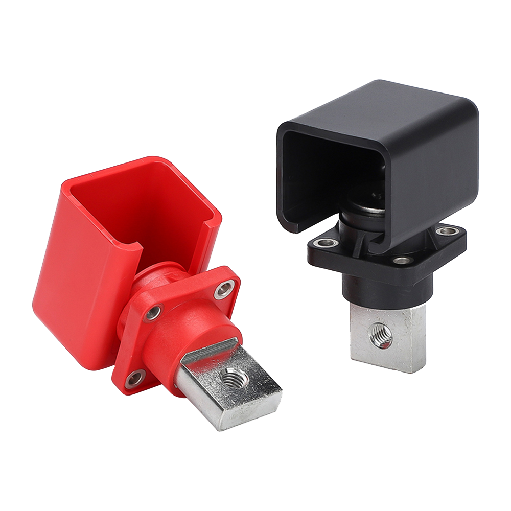
The MCS connector must combine high-voltage insulation, high-current conduction, mechanical durability, reliable locking, temperature monitoring, and touch protection.
At 3,000 A, even small contact resistance can generate significant heat, making contact geometry, materials, sensing, and cooling critical.

MCS vehicle inlet and charging connector from Stäubli, developed to CharIN standards
Source: By SRago91 – Own work, CC BY-SA 4.0, https://commons.wikimedia.org/w/index.php?curid=182124822
2. Liquid-Cooled MCS Cables
Cable heating follows the same basic relationship:
Ploss = I2R
At several thousand amperes, these losses can produce substantial heat. Liquid cooling removes heat through coolant channels, allowing the cable to carry high current without becoming excessively large and heavy.

Cross-sectional structure diagram of high-power EV liquid-cooled charging cable
Source: OMG EV Cable
3. High-Efficiency Power Electronics
Megawatt chargers typically use modular power-conversion systems rather than a single oversized converter. Modular designs can scale output, distribute load, simplify maintenance, and improve thermal management.
Silicon carbide (SiC) semiconductors are also attractive for high-power conversion because of their switching and efficiency characteristics.

Arrow-Infineon 30kW Industrial DC Fast Charger Reference Design Platform
Source: https://www.eetasia.com/arrow-electronics-and-infineon-partner-to-accelerate-development-of-ev-chargers/
4. Dynamic Power Sharing
Multiple MCS chargers could theoretically require several megawatts at the same time. Because grid capacity may be limited, an energy-management system can distribute available power according to vehicle demand, SOC, departure time, grid capacity, battery storage, and charging priority.

Dynamic power sharing among multiple EVs
Source: https://www.linkedin.com/posts/lukaszbancarzewski_sicharge-siemens-elektromobilnoagjafd-share-7171050940618199042-Ud8x/
5. Battery Energy Storage Integration
Battery energy storage systems can buffer peak charging demand and supplement limited grid capacity.
A simplified architecture is:
Grid + Solar → BESS → MCS Chargers → Electric Trucks
BESS can also reduce grid power spikes and store renewable energy, making it useful for high-utilization charging hubs.

Architecture of a Grid-Connected Solar and Battery Microgrid Charging Station
MCS Protection and Safety Design
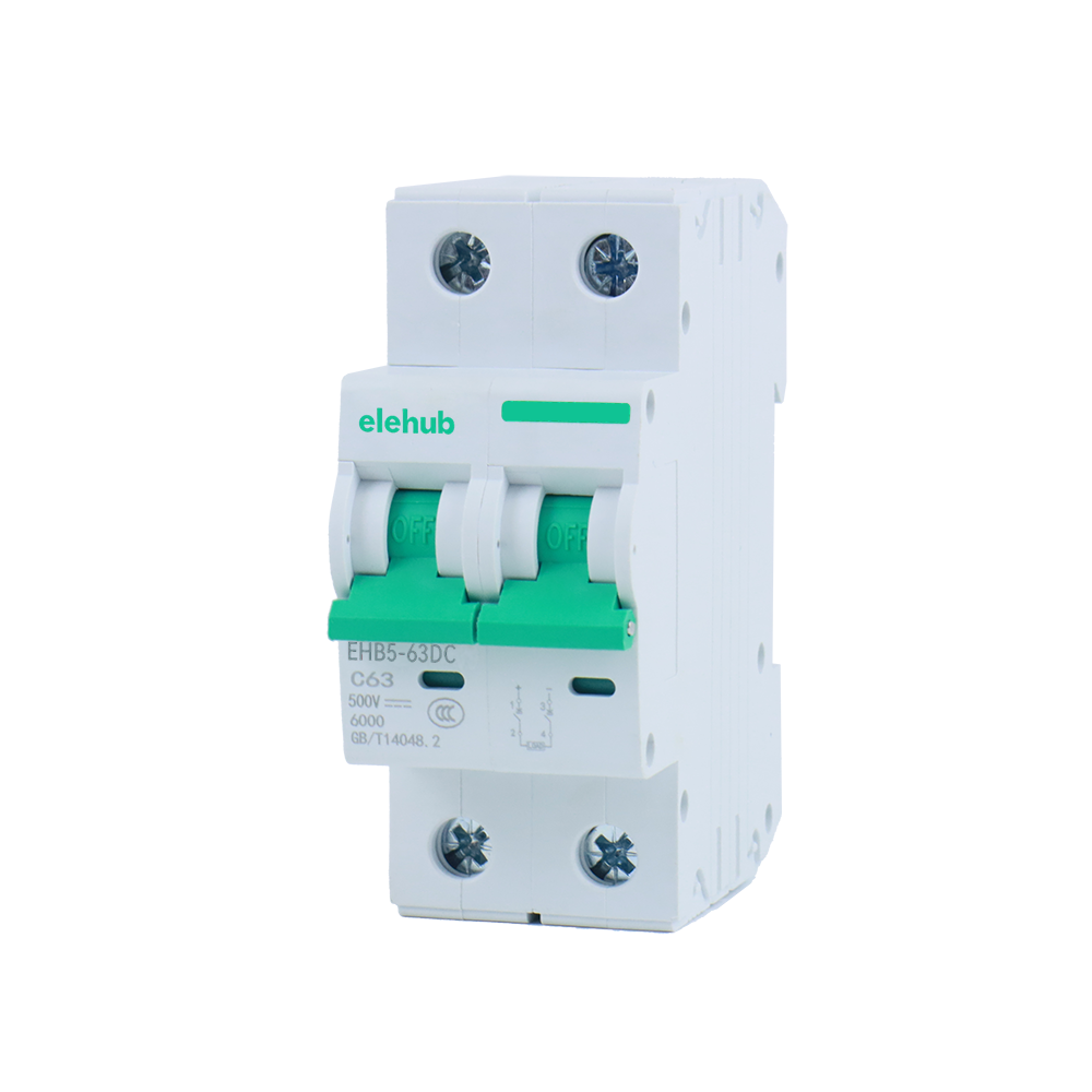
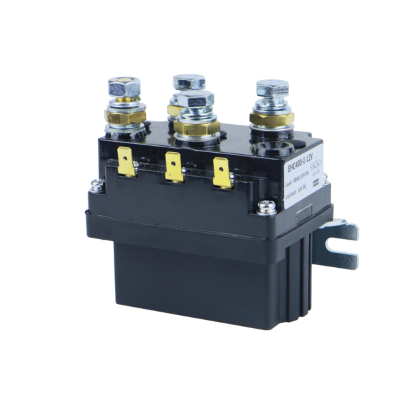
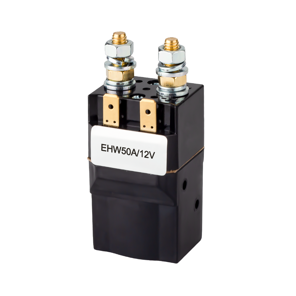
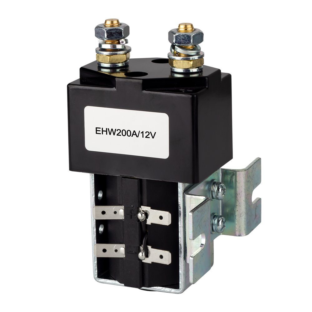
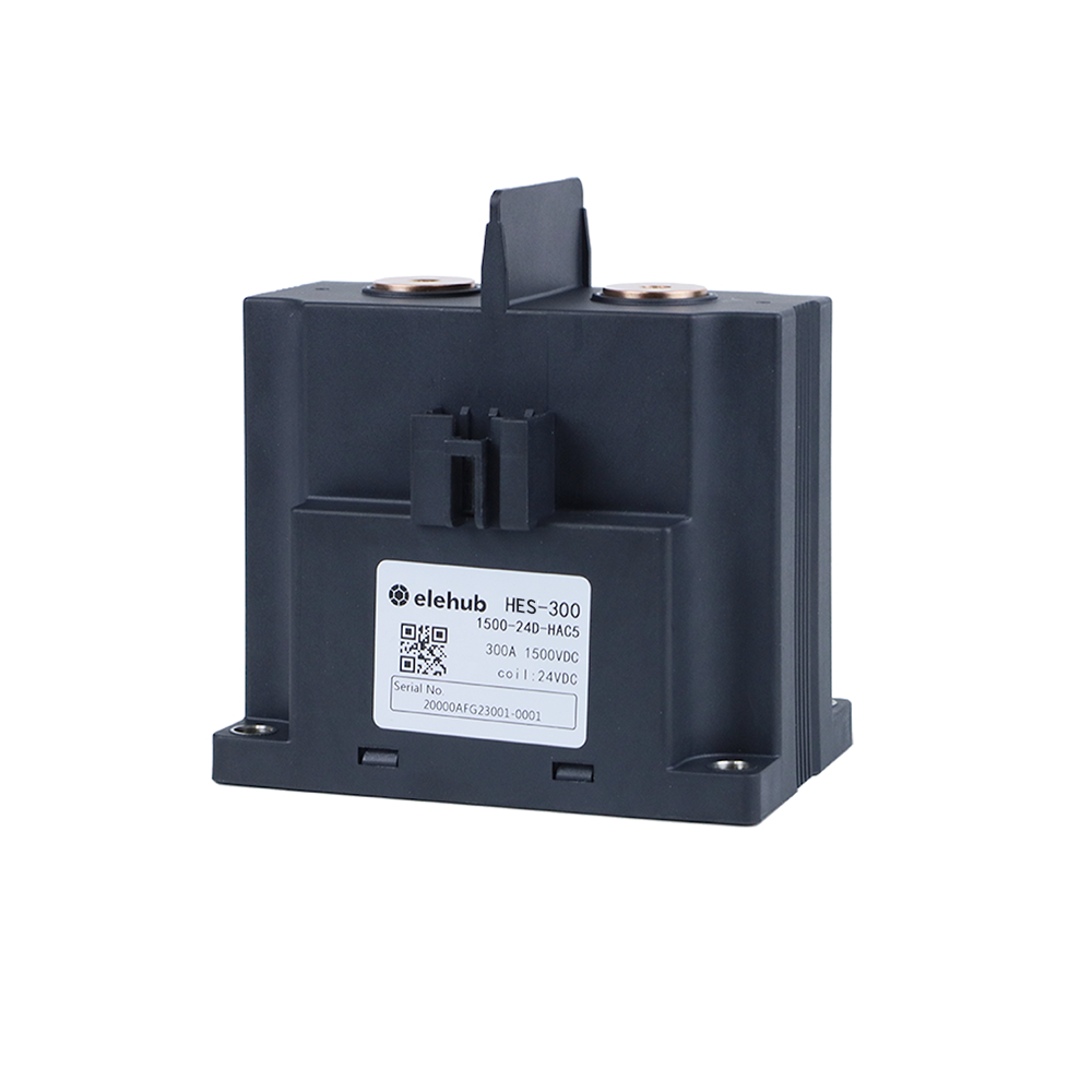
At 1,000-plus volts and kiloampere-scale current, protection must be coordinated across interrupting capability, isolation, sensing, switching sequence, and fault energy. That is the point where high-voltage DC contactors, DC fuses, circuit breakers, and DC surge protection devices become appropriate around conversion stages and the DC bus.
| Protection Device | Primary Function |
|---|---|
| HVDC Contactor | Controlled switching/isolation |
| DC Fuse | Fast high-fault interruption |
| DC Circuit Breaker | Resettable interruption/isolation |
| Pre-charge Contactor | Inrush current control |
| DC SPD | Transient overvoltage protection |
| Insulation Monitor | Detect insulation faults |
1. Overcurrent and Short-Circuit Protection
Fault energy rises brutally at megawatt power. CharIN’s 2025 white paper recommends that the vehicle limit a prospective DC+ to DC- short-circuit peak to 70 kA and 12 MA²s. The EVSE should limit peak current at the vehicle connector to 30 kA and 1 MA²s. The EV, EVSE, locked coupler, and protective devices must be coordinated around those conditions.
👉 Further Reading:
Fuse vs Circuit Breaker: Key Differences Explained
Automotive High Voltage Contactor for EV and HEV: Working Principle and Applications
2. Pre-Charge Protection
Closing a main contactor onto uncharged DC-link capacitance can create severe inrush current. A typical pre-charge circuit inserts a resistor or controlled current path first. This allows downstream capacitance to approach the source voltage. Once the voltage difference falls inside the permitted window, the main contactors can close, and the pre-charge path is bypassed.

Typical EV Pre-Charge Circuit with Resistor and Contactors
Source: https://www.batterydesign.net/electrical/high-voltage-system/contactors/
That sequence is inside a larger state machine that also checks locking, insulation, communication, voltage matching, and thermal readiness. The MCS safety concept calls for a galvanically isolated system and coordinated high-voltage safeguards before energy transfer.
3. DC Arc Protection
DC interruption is unforgiving because there is no natural current zero crossing every half-cycle as there is with AC. If contacts separate while considerable DC current is flowing, the arc has to be extinguished by hardware that is engineered for the DC voltage and fault level.
Fuses, breakers, contactors, clearances, and disconnects therefore need DC ratings that are in accordance with the actual system voltage and prospective fault current.

4. Thermal and Insulation Protection
MCS uses a galvanically isolated charging architecture. Touch-safe construction and IPXXB protection help to stop users from touching high-voltage parts during connector handling.
Sensors at the connector and inlet monitor contact temperatures. This allows the controller to reduce current as thermal margin shrinks. A charger that is capable of 3,000 A electrically may thus deliver less in hot conditions or when the vehicle requests a lower rate.

MCS Connector Internal Structure & Thermal Protection
Source: https://www.evengineeringonline.com/why-ev-engineers-are-turning-to-liquid-cooled-charging-systems/
5. Surge Protection, Grounding, and Interlocks
Fast transients from lightning or switching need a different layer from overload protection. DC surge protection devices (SPDs) limit transient overvoltage before it reaches vulnerable electronics. They complement, not replace, fuses and breakers. Protective-earth continuity, insulation monitoring, connector locking, and emergency-stop logic complete the chain.
Communication, Control, and Energy Management
MCS changes the charging-session “language” as well as the connector.
10BASE-T1S
CharIN endorses 10BASE-T1S single-pair Ethernet on dedicated MCS communication pins. The reason is electrical, not fashionable networking. MCS was designed for six times the current and up to ten times the power of CCS. So, CharIN judged the existing single-ended power-line communication approach insufficient for the expected electromagnetic environment.
ISO 15118-20
Above that physical layer comes ISO 15118-20. It provides IP-based EV-to-EVSE communication and enables functions including more sophisticated charging management and bidirectional power transfer.
In July 2026, ISO published ISO 15118-20:2022/Amd 1:2026, which adds MCS service and an improved security concept in an explicit manner. Annex K contains requirements for digital communication with the Megawatt Charging System.
EV–EVSE Power Negotiation
During charging, the EV and EVSE continuously operate within mutually acceptable electrical and thermal limits. The EVSE communicates its maximum voltage, current, available power, and thermal constraints, while the vehicle provides its requested charging parameters, battery limitations, and charging status.
This creates a closed-loop charging process in which the actual power is determined by the negotiated operating point. Therefore, available charger power does not necessarily equal actual vehicle charging power.
Smart Charging and Fleet Energy Management
At a fleet charging site, communication extends beyond individual vehicle–EVSE sessions. A site energy management system can coordinate multiple charging sessions based on departure schedules, vehicle SOC, grid constraints, BESS availability, and renewable generation.
This allows operators to prioritize vehicles based on operational needs instead of supplying maximum power to every truck simultaneously. The result can be better utilization of available site power and reduced peak demand.
Applications of Megawatt Charging Systems
The first target is Class 6, 7, and 8 battery-electric commercial vehicles, and the main focus is long-haul tractors. The architecture is also good for other very large batteries with short dwell times. If we talk about CharIN’s scope, it centers on heavy commercial vehicles and identifies buses, electric aircraft, ferries, and large-battery applications as potential extensions.

Megawatt Charging Station Layout for Heavy-Duty Electric Trucks
Source: Andy Sproles/ORNL, U.S. Dept. of Energy
Likely MCS applications include:
- Highway electric-truck charging hubs
- Fleet depots with narrow turnaround windows
- Distribution and logistics centers
- Port and drayage operations
- Electric buses and long-distance coaches
- Selected mining and off-road vehicles
- Marine vessels and future high-energy aviation applications
Not every fleet is in need of MCS, though. For instance, a delivery truck that is parked for 10 hours every night might be more economically served by lower-power charging. When time is of genuine operational worth, megawatt EV charging is able to earn its keep.
MCS Standards and Industry Development
The megawatt charging standard has moved to formal international specs in stages.
| Standard | Year | Key Contribution |
|---|---|---|
| CharIN MCS | 2018 | Developed the MCS framework and interoperability requirements |
| SAE J3271 | 2025 | Provided guidance on couplers, communication, cooling, automation, and interoperability |
| IEC TS 63379 | 2026 | Specified MCS vehicle connectors, inlets, and cable assemblies |
| ISO 15118-20 Amendment | 2026 | Added dedicated MCS communication provisions |
The MCS deployment status in 2026 is also different from just a few years ago. The technology is no longer confined to lab demos. Germany’s HoLa project opened the country’s first public MCS point at Lipperland Süd on September 29, 2025. Fraunhofer reports charging power up to 1.2 MW, with the project targeting hundreds of km of added truck range in 30-45 minutes.
Policy is creating demand even when it does not mandate MCS by name. Under the EU Alternative Fuels Infrastructure Regulation, by 2025 heavy-duty charging pools were needed along at least 15% of the TEN-T road network, with at least 1,400 kW aggregate output per qualifying pool and one 350 kW point. For 2030, core-network pools are targeted at 3,600 kW aggregate output, including at least two 350 kW points, at intervals no greater than 60 km.
One important point is worth clarifying: EU AFIR does not require Megawatt Charging System charging for passenger cars. Its infrastructure targets distinguish light-duty and heavy-duty vehicles. MCS standardization is driven by high-energy commercial applications.
Future Trends of Megawatt Charging
The next phase will not have to prove that a 1 megawatt EV charger works. However, it will be more about making fleets, grids, batteries, and stations work together at scale.
More Flexible Real-World Charging Power
Real-world power will diversify. Even 1-1.2 MW can alter long-haul schedules. Higher output makes sense only when batteries can accept it repeatedly as well as site economics support it. Consequently, the 3.75 MW figure is better viewed as an interoperability envelope than an instruction to run every session at maximum power.
Charging Plazas Will Become Energy Systems
Storage, solar, dynamic power sharing, queue-aware charging, and utility coordination can tame peak load. DOE’s investment in MCS-compatible truck hubs with megawatt-scale battery storage already points in this direction.
Stronger Interoperability and Automated Charging
Interoperability will get tightened as IEC, ISO, SAE, vehicle makers, and charger suppliers validate common interfaces in real service. Automated charging may be attractive in depots. Note that CharIN already requires MCS architecture to remain capable of automation, and its connector geometry has been developed with automated connection in mind.
Conclusion
Heavy transport runs on a different clock from passenger mobility. The success of the Megawatt Charging System will be judged less by lab peak power than by daily freight operations.
As standards settle and public deployments accumulate, the question will change its direction from “Can we charge at a megawatt?” to “Can we do it reliably, repeatedly, and economically every day?” That is where ultra-fast electric-truck charging will be decided.
FAQs
What types of electric trucks are compatible with MCS?
MCS primarily supports heavy-duty battery-electric trucks with large batteries, high daily mileage, and short charging windows. Actual compatibility depends on vehicle hardware, software, inlet design, and communication requirements.
Can existing EV charging stations be upgraded to MCS?
Some sites can be upgraded, but MCS usually requires new high-power equipment, larger electrical infrastructure, upgraded switchgear, thermal management, and compatible communication systems rather than simply replacing the connector.
How much does an MCS charging station cost?
MCS station costs depend on charger power, number of stalls, grid connection, transformers, construction, cooling, energy storage, and equipment requirements. Larger sites generally require substantially greater investment.
Does MCS require a medium-voltage grid connection?
Not necessarily. However, high-power MCS sites may require medium-voltage service depending on local utility infrastructure, total charging demand, transformer capacity, and the site’s maximum simultaneous power requirements.
Will MCS charging damage an electric truck battery?
MCS itself does not inherently damage batteries. Charging rates are controlled according to vehicle limits, temperature, battery condition, and manufacturer strategies. Battery aging still depends on charging frequency and operating conditions.
Can MCS chargers dynamically share power between multiple trucks?
Yes. Intelligent energy-management systems can dynamically distribute available power among multiple trucks according to vehicle demand, site capacity, charging priorities, and equipment limits, improving overall station utilization.
Can battery energy storage make MCS charging easier to deploy?
Battery energy storage can reduce grid demand peaks and supplement available power during simultaneous charging. This may reduce required grid capacity, although storage economics depend on electricity rates, utilization, and local conditions.
Does MCS work with different truck manufacturers?
MCS standardization is designed to improve interoperability across manufacturers. However, successful charging still depends on compatible vehicle hardware, EVSE implementation, communication software, testing, certification, and manufacturer-specific requirements.
Can MCS chargers support bidirectional charging?
MCS is being developed to support bidirectional power transfer. Actual vehicle-to-grid capability depends on the truck, charger, communication implementation, grid requirements, and applicable standards.