For measuring current flow in circuits, two commonly used techniques or devices are the shunt resistor, which is a low-resistance component used to measure current by producing a voltage drop, and the Hall effect sensor, which detects magnetic fields to measure current without direct electrical contact. Both have their own features and limitations, and their use depends on the project and circuit requirements. In this tutorial, we will discuss Hall effect current sensor vs shunt resistor and highlight their key differences.
📍 Quick Comparison & Summary
| Feature | Hall Effect Sensor | Shunt Resistor |
| Measurement Principle | Magnetic field detection | Voltage drop via Ohm’s law |
| Isolation | Galvanic isolation | No |
| AC/DC | Both | Both |
| Accuracy | Moderate | High |
| Cost | Higher | Low |
| Response Time | Fast | Very fast |
- Hall effect sensors detect magnetic fields to measure current without direct contact, offering galvanic isolation and safety for high-voltage applications.
- Shunt resistors measure current via a small voltage drop, providing high precision at low cost, ideal for low- to medium-current applications.
- Choosing the right device depends on current range, isolation needs, accuracy, and system type.
What Is a Hall Effect Current Sensor?
The Hall effect current sensor is used to measure current by detecting the magnetic field produced around a current-carrying conductor. It does not measure current directly but follows the Hall effect phenomenon to measure current accurately.

Compared to a shunt resistor, which measures current through a direct electrical connection, a Hall effect current sensor measures current indirectly. When current flows through a conductor, it produces a magnetic field proportional to the current. The non-invasive Hall effect current sensor detects this magnetic field and converts it into an electrical signal that indicates the magnitude and direction of the current.
One key advantage is that a Hall effect sensor allows current to flow through a conductor without the sensor itself carrying the current directly. This provides galvanic isolation between the measurement path and the output signal, creating a safer system and protecting sensitive components in high-voltage and high-current applications.
The Hall effect current sensor can measure both AC and DC current. This capability makes it useful in applications such as power converters, automation systems, motor drivers, and advanced motion-control systems like servo motors.
Hall Effect Current Sensor Working Principle
A Hall effect current sensor operates by detecting the magnetic field generated by current and converting it into an electrical signal. This process allows the sensor to measure current without a direct connection to the conductor.
The working process of the Hall effect sensor is explained here:
1. Magnetic Field Generation
When current flows through a conductor, a magnetic field is generated according to Ampere’s law. To produce the required signal, the current-carrying conductor is placed close to the Hall sensing component so that the magnetic field can be detected accurately.

By User:Stannered – Image:Electromagnetism.png, CC BY-SA 3.0,
https://commons.wikimedia.org/w/index.php?curid=1646467
2. Detection of the Magnetic Field by the Hall Element
The main component of the sensor is the Hall element, which is a semiconductor device that operates according to the magnetic field. When a magnetic field is generated by the current, the Hall element produces a voltage called the Hall voltage. This voltage is directly related to the magnetic flux density and the current flowing in the conductor.
3. Electrical Output Signal Generation
The Hall voltage produced by the sensing element is very small and requires amplification. The internal signal-conditioning circuit performs amplification and filtering and converts it into a linear signal to provide a stable output.
The output depends on the sensor design:
- Analog voltage that is directly proportional to the measured current.
- Analog current output for industrial control systems.
- Digital signal for monitoring and protection systems.
Structure
A Hall effect current sensor consists of several components, including:
- Primary conductor – The path through which the current flows, generating a magnetic field around it.
- Magnetic core – Concentrates the magnetic field
- Hall sensing element – Detects changes in the magnetic field generated by variations in current
- Signal-conditioning circuits – Amplify the signal to produce an output, which can be either digital or analog
Types of Hall Effect Current Sensors
A Hall effect sensor for current measurement comes with open-loop and closed-loop configurations:
- Open-loop Hall effect current sensor: Used to measure the magnetic field of the current. It has a simple design, low power consumption, and low cost.
- Closed-loop Hall effect current sensor: Employs a compensation coil to cancel the magnetic field produced by the current. By providing nearly zero flux in the core, the closed-loop sensor offers a high-speed response, better accuracy, and stable temperature performance, making it suitable for motor control applications.
Advantages
- Non-contact measurement (safe and isolated)
- Measures both AC and DC current
- Suitable for high current (100A, 200A+)
- Supports AC and DC measurement
- Low insertion loss (minimal power loss)
- Ideal for automotive and high-voltage systems
Disadvantages
- Higher cost than shunt resistors
- Lower accuracy (open-loop types) compared to precision shunt solutions
- Sensitive to external magnetic interference
- Offset drift due to temperature changes
- Requires calibration in high-precision applications
- Larger physical size compared to compact shunt resistors
Applications
Since measurement is based on magnetic field interaction rather than a direct electrical connection, a Hall effect sensor provides galvanic isolation between the current path and the output signal. This makes it especially suitable for high-voltage and high-current environments, ensuring system safety and protecting sensitive electronics.
With the ability to measure both AC and DC current and deliver high-speed response, these sensors are widely used in applications that require real-time current feedback, accurate control, and high efficiency.
They are commonly applied in the following fields:
- Electric vehicles (EVs) – A Hall effect current sensor automotive solution is used in battery management systems (BMS), motor drives, and charging systems to monitor current flow, ensuring safe operation and optimized energy usa
- Power converters & inverters – Provide precise current feedback in DC-DC converters and DC-AC inverters, enabling efficient power conversion and reliable control of switching devices.
- Renewable energy systems – Widely used in solar inverters and wind power systems to monitor current, improve energy conversion efficiency, and ensure stable operation.
- Industrial automation & motor drives – Using Hall effect sensor to measure current allows accurate torque control and fast response in servo systems and motion control applications, improving system reliability and performance.
What is a Shunt Resistor?
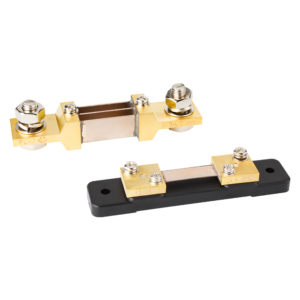
A shunt resistor is connected in series with a circuit to provide a precise measurement of current. It measures current by producing a small voltage drop across its terminals that is directly proportional to the current.
The voltage drop across the terminals is measured using Ohm’s law, which helps determine the current flow without significantly affecting the circuit’s operation.
Shunt Resistors Working Principle
The working principle of a shunt resistor is simple. It is connected in series with the circuit being measured so that a small current flows through it. This process is important for accurate current measurement.
1. Ohm’s Law and Current Calculation
The operation of a shunt resistor is based on Ohm’s law. By knowing the resistance value, the current flowing through the shunt can be calculated from the voltage drop across it.
The equation is: I = V / R, where I is the current in amperes, V is the voltage, and R is the resistance.
2. Voltage Drop
When current flows through the shunt resistor, a small voltage drop occurs across it. This voltage drop is proportional to the current flowing in the circuit. By measuring this voltage drop, the current in the main circuit can be determined without significantly affecting its operation.
3. Small Signal Amplification
In some applications, the voltage drop across the resistor is very small. To obtain a proper detection signal, the voltage is amplified. This amplification helps provide accurate measurements and allows the signal to be used by control and measurement systems.
Structure
A shunt resistor typically includes:
- Resistive element made of manganin alloy – Has very low resistance, usually in the micro-ohm range, which helps ensure low power dissipation and minimal voltage drop
- Two terminals with specific connection points – Carry the main current through the resistor
- Four‑terminal Kelvin connections (optional) – In many high‑accuracy designs, a shunt resistor uses four distinct terminals to obtain accurate measurements by separating the current and voltage paths.: two for the high‑current path and two separate sense terminals for measuring the voltage drop
Advantages
- High precision and stability
- Low cost and simple implementation
- Small size (SMD options available)
- Fast response time
- Ideal for low-current measurement
Disadvantages
- No electrical isolation (direct connection required)
- Power loss due to heat dissation (I²R loss)
- Limited performance in high-voltage systems
- Accuracy affected by temperature rise
- Not ideal for very high current without thermal management
Applications
Shunt resistors for current measurement are widely used in systems that require direct, accurate current measurement:
- Power supplies & DC-DC converters – Monitor output current for regulation and protection
- Battery management systems (BMS) – Measure charge/discharge current for safe battery operation
- Electric vehicles (EVs) – Track battery current and detect faults in real time
- Motor control & robotics – Provide current feedback for torque and speed control
- Industrial automation systems – Enable precise monitoring and overload protection
- Energy meters & measurement instruments – Ensure accurate power consumption tracking
- Inverters & UPS systems – Support power monitoring and system stability
- Solar energy systems – Monitor current in PV panels, batteries, and controllers for efficiency and protection.
⭐️ Further Reading: What Is a Shunt Resistor? The Ultimate Guide to Its Basics & Applications
Hall Effect Current Sensor vs Shunt Resistor: Key Differences

|
Features
|
Hall Effect Current Sensor
|
Shunt Resistor
|
|
Measurement Principle
|
Measures current via magnetic field generated by conductor
|
Measures current via voltage drop across a low‑value resistor (Ohm’s law)
|
|
Electrical Isolation
|
Provides galvanic isolation between the measured circuit and the output
|
No isolation
|
|
Power Loss
|
Very low insertion loss
|
Higher power loss due to I²R dissipation
|
|
Heat Production
|
Less
|
Significant at high currents
|
|
Accuracy
|
Moderate accuracy, can be affected by temperature and external magnetic fields
|
High accuracy with precision resistors
|
|
Current Range
|
Suitable for wide current range, including high currents
|
Best for low to medium currents (high‑current requires careful design/thermal management)
|
|
AC/DC Capability
|
Both AC and DC
|
Both AC and DC
|
|
Response Time
|
Slower response (µs range) due to electronics and magnetic sensing limitations
|
Very fast (ns–µs range); wide bandwidth (good for high‑frequency signals)
|
|
Signal Conditioning
|
Integrated signal conditioning common, output is often conditioned internally
|
Often needs external amplifier (to measure very small V)
|
|
Cost
|
Higher cost (core + electronics)
|
Low cost; simple implementation
|
|
Size / Integration
|
Generally larger due to core and sensing electronics
|
Compact for low current; high‑power shunts can be bulky
|
|
Installation
|
Non‑intrusive; easy to install without breaking circuit path
|
Requires series connection; may require careful layout and heat management
|
|
Safety
|
Better safety due to galvanic isolation
|
Lower in high‑voltage applications (no isolation)
|
When to Choose a Shunt Resistor
- High measurement accuracy, especially at low to medium currents.
- Low cost and simple implementation.
- Fast response time and wide bandwidth.
- To measure current directly using a simple interface.
Typical applications include low‑voltage power supplies, battery management systems, and precision measurement circuits.
When to Choose a Hall Effect Current Sensor
- Galvanic isolation for high‑voltage systems.
- Non‑contact measurement without breaking the circuit.
- To measure very high currents with minimal power loss.
- A solution that works for both AC and DC without direct electrical connection.
Hall sensors are well suited for high‑voltage power electronics, electric vehicles, industrial automation, and renewable energy systems where safety and isolation are priorities.
If you’d like to explore current sensors in more detail, check our comprehensive guide: Types of Current Sensors.
How to Select the Right Shunt Resistor
To ensure optimal results, several key factors must be considered during selection:
1. Required Resistance Value Calculation
First, determine the resistance value of the shunt resistor. This value depends on the maximum current and the allowable voltage drop across the resistor terminals. A low resistance value allows the measurement of high current with a small voltage drop, which helps measure current accurately without significantly affecting the circuit.
2. Power Rating
The power rating of a shunt resistor indicates its ability to handle heat when current flows through it. Power dissipation can be calculated using the equation P = I²R, where I is the current and R is the resistance. Select a shunt resistor with a power rating higher than the calculated dissipated power to ensure safe operation and avoid overheating.
3. Resistance Temperature Coefficient
This factor shows how the resistance changes with temperature. A low Temperature Coefficient of Resistance (TCR) reduces measurement errors when temperature varies. For highly accurate results, a shunt resistor with a low TCR is preferred. Materials such as manganin and zeranin alloys provide low TCR characteristics.
4. Physical Dimensions
Check the available space in the circuit and the mounting requirements before selecting a shunt resistor. Larger resistors can handle higher power dissipation but may not fit in compact layouts. Therefore, choose a shunt resistor with suitable terminals or mounting options for easy installation on the PCB.
ELEHUB’s Shunt Resistor
|
Model
|
Current Range
|
Voltage Drop
|
Accuracy Class
|
 |
75-200A, 250-300A, 400-1000A
|
50mV, 60mV, 75mV
|
0.5%, 0.2%
|
|
|
1-50A, 75-100A, 150-600A, 750-1500A, 1500A-2500A, 3000-6000A
|
50mV, 60mV, 75mV
|
0.5%, 0.2%
|
 |
100-150A, 200A, 300A, 400-600A
|
50mV, 75mV
|
0.5%, 0.2%
|
 |
5-150A, 170-600A , 800-1200A
|
50mV, 60mV, 75mV, 100mV
|
0.5%, 0.2%
|
 |
1-25A, 30-150A, 200-300A, 400-800A, 1000-1200A, 1500-2000A, 2500A, 10000A
|
50mV, 60mV, 75mV, 100mV
|
0.5%, 0.2%
|
 |
1-60A
|
50mV, 60mV, 75mV, 100mV
|
0.5%, 0.2%
|
 |
100-200A, 300A, 400A, 500-600A, 750A, 1000A, 1500A
|
50mV, 60mV, 75mV, 100mV
|
0.5%, 0.2%
|
 |
5-125A, 150-200A, 250-600A, 800-1500A, 2000-2500A, 3000-6000A
|
50mV, 60mV, 75mV, 100mV
|
0.5%, 0.2%
|
|
|
50-300A , 500A , 750A–4000A
|
25mV, 30mV, 50mV, 60mV, 75mV
|
0.2%, 0.1%
|


Elehub’s Split-Core Hall Effect DC Current Sensor
| Model | Rated Current | Output Voltage | Power Supply | Hole Diameter |
|
HSTS21
|
±50/100/200/300/400/500/600 A | 2.5 V ± 0.625 V | +5 V | 21 mm |
|
HSTS30
|
±100/300/500/600/800/1000 A | 2.5 V ± 0.625 V | +5 V | 30.5 mm |

Conclusion
Each shunt resistor and Hall effect sensor has its importance for current measurement. A shunt resistor is a low-cost option for low-current and low-frequency projects, while a Hall effect sensor is suitable for high-frequency and high-current applications.
By understanding the features of both devices, we can make practical recommendations for their use. For accurate DC current measurement in battery and power charging systems, Elehub DC shunt resistors provide high accuracy and durability.
By combining Elehub’s high-accuracy shunt resistors with Hall effect current sensors, users can achieve current measurement solutions that balance precision, safety, and system requirements for a wide range of electrical and power applications.
FAQs
What is the main difference between a Hall effect sensor and a shunt resistor?
Hall sensors measure current indirectly via magnetic fields with isolation, while shunt resistors measure current directly via voltage drop.
Can Hall effect sensors measure both AC and DC currents?
Yes, they are suitable for AC and DC applications.
Are Hall effect sensors safe for high-voltage systems?
Yes, galvanic isolation ensures safety for high-voltage and high-current applications.
Does a Hall effect sensor generate its own current?
No, a Hall effect sensor does not generate current. It produces a small voltage called the Hall voltage when exposed to a magnetic field from a current-carrying conductor. This voltage is proportional to the current and requires a supply voltage and signal conditioning for measurement.
What are shunt resistors in moving coil meters used for?
Shunt resistors in moving coil meters allow measurement of currents higher than the meter’s coil rating. They are connected in parallel with the coil to bypass most current, protecting the instrument and enabling accurate current measurement based on the known resistance of the shunt.
Why shunt resistor is used in ammeter?
A shunt resistor for ammeter measures current by creating a small, precise voltage drop proportional to the current flowing through it. This allows the ammeter to calculate current accurately without significantly affecting the circuit, providing a simple, low-cost, and reliable measurement solution.