The electrical chain inside a data center used to be fairly predictable. Medium-voltage utility AC entered the site, transformers stepped it down, UPS converted it through a DC battery link and back to AC, and rack power supplies changed AC into the low-voltage DC used by processors.
That arrangement is dependable, but AI has changed the problem. U.S. data centers consumed 176 TWh in 2023, up from 58 TWh in 2014, and Berkeley Lab projects usage of 325-580 TWh by 2028. Globally, the IEA expects data-center electricity demand to reach 945 TWh in 2030.
The pressure is not only about total energy. It is also about density. AI racks are moving from tens of kilowatts toward hundreds of kilowatts, and new open architectures are being designed for loads approaching 1 MW. At that point, familiar 48/54 V rack buses, repeated conversion stages, and bulky copper paths are difficult to scale. That is the reason why data center power distribution is going to centralized 380 VDC, ±400 VDC, and 800 VDC architectures.

By Tedder – Own work, CC BY-SA 4.0, https://commons.wikimedia.org/w/index.php?curid=135864697
Understanding High-Voltage DC Power Systems
A terminology note is important here. The data-center industry often calls 380-800 VDC “HVDC” since it is high voltage when compared to a 48 or 54 V rack bus.
The underlying concept is the following:
- Convert incoming AC to DC at a centralized power stage.
- Distribute DC at a sufficiently high voltage to control current.
- Perform the necessary DC/DC conversion near the computing load.
A 380V DC data center sends a unipolar or bipolar DC supply to compatible equipment. Newer 800V DC data center proposals use either a two-wire 800 V feed or a three-wire ±400 V arrangement. The voltage is cut to 48/54 V, 12 V, or another intermediate level inside the IT rack.
The Open Compute Project’s Diablo specification, in which Google, Meta, and Microsoft also participated, describes sidecar power racks that deliver ±400 VDC or 800 VDC to high-density IT racks. The architecture is intended to serve rack loads from 100 kW to 1 MW.

Simplified Data Center Power Distribution Diagram
A DC power distribution data center does not necessarily receive direct current from the public grid. In most near-term projects, the utility connection is AC. The difference appears after the facility entrance when one controlled conversion creates the internal DC backbone.
Traditional AC Path
Utility MV AC
→ transformer and switchgear
→ UPS rectifier
→ battery DC link
→ UPS inverter
→ AC PDU or busway
→ rack AC/DC power supplies
→ 48/54 VDC bus
→ point-of-load converters

Data Center AC Power Flow Architecture
Facility-level HVDC Path
Utility MV AC
→ transformer or solid-state front end
→ centralized rectifier
→ 380/800 VDC bus with energy storage
→ DC protection and distribution
→ rack DC/DC converter
→ processor voltage rails
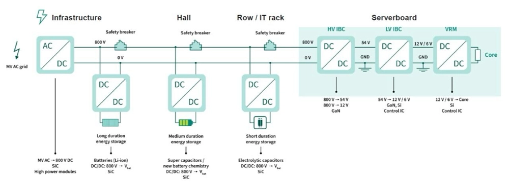
Data Center DC Power Flow Architecture
Source: Infineon
Why Traditional AC Systems Are No Longer Enough
AC is not suddenly obsolete. It benefits from mature switchgear, familiar protection practices, standardized maintenance procedures, and an enormous installed base.
Problems come to the surface when an electrical architecture that was basically designed around 10-30 kW racks is stretched to supply AI systems several times denser.
Low-Voltage Distribution Creates Excessive Current
Formula: P=VI
Consider a simplified 1 MW rack:
- At 48 V, delivering that power would require 1,000,000 W / 48 V = 20,833 A
- At 800 V, the required current falls to 1,000,000 W / 800 V = 1,250 A
In real-world scenarios, systems may divide the load across several feeds, conductors, and converter modules, but the calculation exposes the basic engineering constraint.
However, this simple calculation reveals a core issue: Increasing the voltage can significantly reduce the transmission current.
AC Skin Effect Becomes More Significant at High Power Levels
Another limitation of AC distribution is theskin effect, where alternating current tends to flow near the outer surface of a conductor rather than using the full cross-sectional area.

AC skin effect: current density decreases from the conductor surface inward.
Source: By Biezl – Own work, Public Domain, https://commons.wikimedia.org/w/index.php?curid=4453931
While this effect is minor in household wiring, it becomes more relevant in large busbars and high-current conductors used in data centers, increasing effective resistance and reducing conductor efficiency. Engineers often mitigate it with stranded conductors, laminated busbars, or optimized conductor geometries.
However, as AI racks move toward hundreds of kilowatts, conventional AC distribution faces increasing challenges. Higher-voltage DC avoids skin effect because current flows uniformly through the conductor, improving power density and distribution efficiency.
High Current Increases Copper Losses and Infrastructure Requirements
Conductor loss follows: Power loss = I²R
For equal resistance, the current-squared loss term at 800 V is 1/278 of the equivalent term at 48 V. Engineers do not receive a magical 278-fold efficiency improvement as conductor sizes and resistances change. Instead, they use the voltage advantage to reduce copper cross-section, lower voltage drops, simplify busbars, or transmit more power through the available space.

OCP contributors estimate that a proposed higher-voltage bus could reduce copper weight by 50%. They also warn that 48 V rack distribution would otherwise require either massive busbars or unacceptable losses as GPU racks climb into the several-hundred-kilowatt range.
Engineer Farhan B. highlighted a 600 kW rack scenario where higher-voltage distribution reduced copper requirements from 373 kg to 22 kg, current from 12,500 A to 750 A, and line losses from 7.9 kW to 0.47 kW, demonstrating the scalability challenges of 48 V systems for high-density AI racks.

Source: Farhan B.
Repeated AC/DC Conversion Creates Additional Energy Losses
Repeated conversion creates another penalty. A double-conversion UPS rectifies AC to DC and then inverts it back to AC. Subsequently, the rack PSU rectifies that power again. Each stage adds heat, components, control circuitry, and possible failure points.
Centralized HVDC sidesteps the rack-level AC/DC stage and allows batteries to remain closer to the primary distribution bus. Along these lines, older Berkeley Lab research cited estimated savings of 7-28% for some 380 VDC systems when compared with 208 VAC designs, although actual outcomes depend on topology, loading, and converter efficiency.
Comparison: Data Center Power AC or DC?
| Design Factor | Conventional AC Distribution | 380/800 VDC Distribution |
|---|---|---|
| Facility Input | Directly compatible with the utility grid | Usually converts incoming AC once through centralized rectifiers |
| Rack Interface | AC rack PDU and server PSUs | High-voltage DC feed and rack DC/DC converters |
| Conversion Chain | More AC/DC and DC/AC stages | Fewer stages between grid and processor |
| High-Power Current | Manageable at 415/480 VAC, but rack PSUs and low-voltage buses become crowded | Lower backbone current for the same transmitted power |
| Energy Storage | Battery is within or beside the UPS chain | Battery or BESS can connect more directly to the DC bus |
| Rack Space | Requires AC/DC power modules inside the rack | Moves large conversion equipment into a sidecar or power room |
| Protection Maturity | Broad standards and technician familiarity | Needs DC-rated interruption, sensing, grounding, and interlocks |
| Current Best Fit | Enterprise, colocation, and mixed legacy loads | New AI/HPC halls, dense clusters, and storage-rich microgrids |
Key Drivers Behind the Shift to HVDC
Rack Density Is Outrunning the 48/54 V Ecosystem
OCP describes rack demand rising from 33 kW into the hundreds of kilowatts. Its Diablo sidecar concept can be configured for power requirements from 800 kW to more than 1 MW.
The same spec provides example DC interconnects of 50 kW at 63 A and 100 kW at 125 A on a ±400 V system. Those power levels would require 1,042 A and 2,083 A at 48 V, respectively.
Centralized Conversion Releases Rack Space
Removing large AC/DC PSUs from computing racks leaves more room for accelerators, networking, liquid-cooling manifolds, as well as service access.
NVIDIA’s proposed architecture converts three-phase AC centrally to 800 VDC and routes it to the rack, and here, DC/DC converters supply the lower voltage rails. NVIDIA estimates an end-to-end efficiency improvement of up to 5% compared with current 54 V systems. That is a vendor projection rather than a guaranteed result, but it indicates the target being pursued.

Batteries and Electronic Loads Are Already DC
Solar arrays, batteries, supercapacitors, power semiconductors, and server electronics all operate internally on direct current. A DC bus can connect these resources with fewer conversions.
Thanks to that arrangement, it’s easier for energy storage to provide ride-through power, peak shaving, or support for rapid GPU load changes. OCP’s LVDC program specifically includes energy storage, startup sequencing, protection interfaces, and hold-up requirements.
👉 Further Reading: Data Center Energy Storage: The Role of BESS in Reliable and Sustainable Power
The EV Industry Has Created a Useful Supply Chain
The change also borrows tech that was developed for electric vehicles and fast charging:
- High-voltage DC contactors
- SiC and GaN power semiconductors
- Touch-safe connectors
- High-speed DC fuses
- 800 V insulation systems
- Precision current sensors

OCP identifies access to the established ±400/800 V EV supply chain as one reason a standardized data-center architecture has become more real-world.
How HVDC Improves Thermal and Water Efficiency
When every watt is lost in rectifiers, inverters, cables, busbars, and power supplies, it eventually becomes heat, and the cooling system must be able to remove that heat.
On a continuously loaded 1 MW rack, when you reduce electrical loss by even only one percentage point, you avoid 10 kW of heat. Over one year, that might equal: 10 kW x 8,760 hours = 87.6 MWh
That is the credible case for DC power for improved data center efficiency. Lower electrical waste cuts both direct usage and the thermal burden surrounding the rack. Removing bulky PSUs and cable bundles can also improve airflow or make room for liquid-cooling hardware.

Typical cold aisle configuration with server rack fronts facing each other and cold air distributed through the raised floor
Source: By Robert.Harker – Own work, CC BY-SA 3.0, https://commons.wikimedia.org/w/index.php?curid=291549
At the same time, DOE guidelines indicate that reducing IT and electrical loads enables related cooling equipment to be downsized or operated less aggressively. NVIDIA establishes a connection between centralized 800 V conversion and lower rack-level cooling pressure.
Yet, water savings are indirect. An evaporatively cooled facility may consume less water when its heat-rejection load falls. A dry-cooled or closed-loop liquid system may show little change in onsite water use. DOE therefore considers Power Usage Effectiveness and Water Usage Effectiveness as separate metrics. HVDC can help both, but the cooling design decides the result.
👉 Further Reading: Data Center Energy Efficiency: PUE, Power Consumption & Best Practices
Critical Components in HVDC Infrastructure
Higher voltage controls current, yet interruption, insulation, isolation, and measurement are less forgiving. OCP’s current requirements include overcurrent protection, ground-fault detection, protective bonding, interlocked access, and adequate creepage and clearance distances.
The figure below illustrates an end-to-end high-voltage DC power delivery architecture from the power room to the GPU rack. Protection devices throughout the system work together to detect faults, limit fault energy, interrupt current, quench arcs, and ensure safe maintenance isolation.

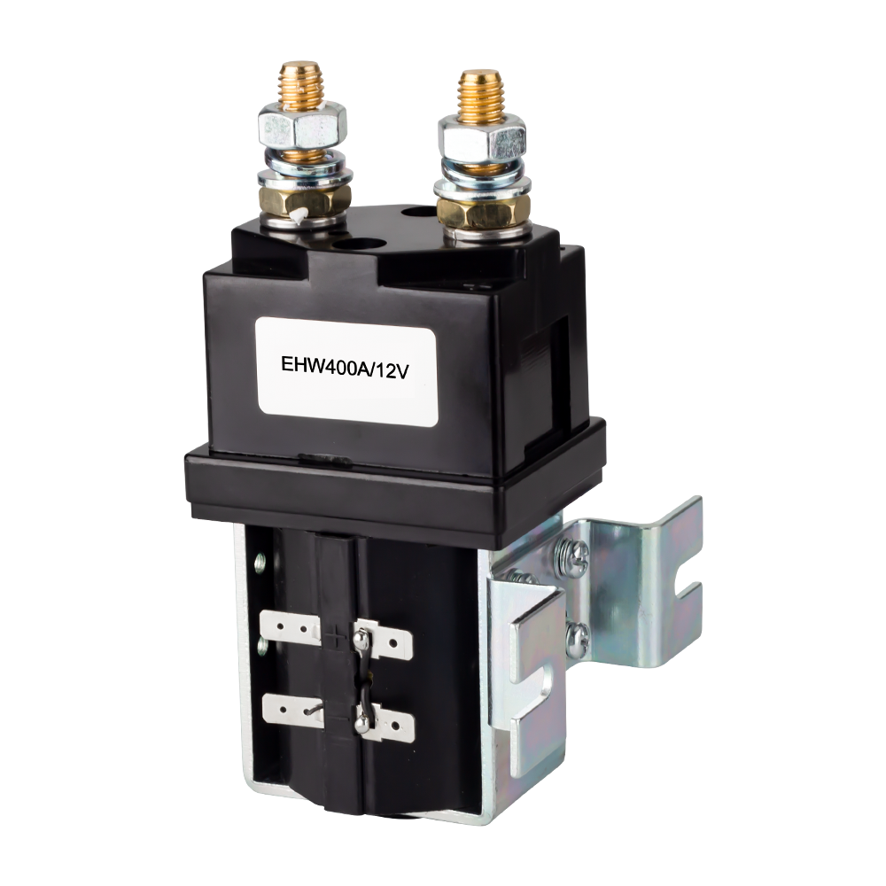
High-Voltage DC Contactor
An HVDC contactor performs controlled switching for:
- Bus energization
- Battery connection
- Rack shutdown
- Redundancy transfer
- Emergency power isolation
Choice must consider operating voltage, continuous current, fault-making capacity, breaking current, polarity, coil voltage, auxiliary feedback, mechanical endurance, and arc energy.
Pre-charge circuitry combines with the main contactor. It charges the rack and converter capacitors through a resistor before the full-power contacts close, to avoid an uncontrolled inrush current.

DC Circuit Breaker
A DC circuit breaker provides resettable overload protection along with short-circuit protection. Unlike alternating current, direct current does not naturally cross zero every half-cycle. As a result, the arc might continue to exist even after the contacts have separated.
DC interruption requires more complex mechanical systems or semiconductor breakers. Solid-state breakers can operate much faster and interrupt current without a conventional contact arc, although conduction loss, cost, heat dissipation, and galvanic isolation are important tradeoffs.

DC Fuse
A high-speed DC fuse limits fault energy before the moment when cables, battery modules, or converter semiconductors exceed their thermal withstand.
Engineers should evaluate:
- Rated DC voltage
- Breaking capacity
- Time-current curve
- Pre-arcing I²t
- Total clearing I²t
- Ambient-temperature derating
- Semiconductor coordination
- Available short-circuit current
A lockable maintenance isolator is not something that can be replaced by a fuse, despite the fact that a fuse is the fastest final layer against a severe bolted fault.

DC Isolator Switch
A DC isolator creates a visible and lockable separation point for servicing. It is normally operated without load unless it is specifically rated as a switch-disconnector.
In an 800 V architecture, mechanical and electrical interlocking are indispensable. Connectors must not be exposed or removed at the time when they are energized, and stored capacitor voltage must fall below the prescribed safe level before access is granted.

Current Shunt
An element with a low resistance that has been calibrated and provides a small voltage that is proportionate to the bus current is called a current shunt. It supports:
- Energy metering
- Load balancing
- Battery state estimation
- Fault detection
- Converter control
- Predictive maintenance
Kelvin connections, low temperature coefficient, pulse withstand, measurement bandwidth, and isolated signal conditioning determine whether readings are accurate during AI load transients.

These devices must operate as a coordinated protection system rather than a collection of parts selected from voltage labels.
Our related portfolio at ELEHUB includes high-voltage DC contactors, DC circuit breakers, DC fuses, DC isolator switches, and current shunts and covers the control, protection, isolation, and monitoring functions around an HVDC bus.

Engineering Challenges of HVDC Systems
Fault Protection and Selectivity
A low-impedance and battery-backed DC bus can supply fault current extremely quickly. Protection must distinguish a rack fault from a main-bus fault, clear the smallest affected zone, and stop parallel converters, capacitors, or batteries from continuing to feed the arc.
It demands coordinated fuse curves, breaker logic, contactor sequences, cable designs, and system-level fault-energy studies. AC protection settings cannot be copied into the new design.
Grounding and Insulation
Designers must choose between solid grounding, high-resistance grounding, and other monitored arrangements. Depending on the option, the touch voltage, first-fault behavior, insulation monitoring, and fault-clearing criteria will all be different.
High-resistance grounding can limit current during a first line-to-ground fault but requires dependable monitoring. Solid grounding simplifies fault location; however, higher fault current and sustained arcing may occur until the protective device operates.
Standardization and Serviceability
The ecosystem still needs consistent rules for:
- Connector geometry
- Voltage tolerance
- Grounding conventions
- Hot-plug behavior
- Pre-charge timing
- Telemetry
- Safe shutdown
- Communication between sidecars and IT racks
Technicians accustomed to AC systems also need procedures for proving a DC bus de-energized, discharging capacitance, applying lockout/tagout, and recognizing persistent DC arcs. NVIDIA identifies standards, workforce training, safety, CapEx, and OpEx as open deployment issues.
Brownfield Migration
An existing facility cannot be converted into a DC data center merely by replacing rack PDUs. The UPS arrangement, generators, maintenance bypasses, fire systems, dual-cord servers, switchgear, and compliance documentation all affect the conversion.
It is more likely that hybrid halls and separate sidecar power systems will make more sense for the majority of existing locations than an instant change that affects the whole complex.
Best Practices for Data Center Power Distribution during Transition
- Model the full electrical chain: Compare transformer, UPS, rectifier, cable, busway, rack converter, and point-of-load losses across realistic operating profiles.
- Calculate DC fault energy early: Include batteries, capacitors, parallel converters, conductor inductance, and protective-device clearing time.
- Select components by actual duty: Check DC voltage, current, short-circuit rating, I²t, insulation coordination, endurance, and temperature increase.
- Build isolation into the mechanical design: Use pre-charge circuits, discharge paths, touch-safe connectors, interlocks, and positive position feedback.
- Coordinate protection layers: DC contactors, breakers, and fuses must isolate faults in the correct order without unnecessarily dropping healthy racks.
- Meter each distribution boundary: Current shunts and isolated voltage sensors should expose losses, load imbalance, abnormal transients, and component aging.
- Plan for AC/DC coexistence: Preserve AC supplies for legacy hardware, as well as deploy HVDC when rack density or storage integration offers a measurable return.
Those are the best practices for data center power distribution. Demonstrate the architecture through system-level measurements and scale it without weakening safety or maintainability.
Future Outlook: Fully DC-Powered Data Centers
The transition will be evolutionary. OCP is in the process of standardizing facility-level LVDC distribution and ±400 V sidecar interfaces. Similarly, NVIDIA says that production deployment of its 800 V architecture might coincide with Kyber rack-scale systems in 2027.
Preliminary adoption will concentrate on greenfield AI factories and high-performance computing halls. However, with the maturity of connectors, DC-rated protection, solid-state transformers, and battery interfaces, the DC boundary may move farther upstream.
At the same time, AC can still remain advantageous for grid interconnection, conventional mechanical loads, office systems, and mixed-use facilities. Successful architecture will not be ideological. It will use each form of power wherever it performs best.
Conclusion
The move toward HVDC is being triggered by an awkward physical fact. Megawatt-class computing cannot be supplied economically through yesterday’s low-voltage rack architecture.
Higher-voltage DC reduces backbone current, relieves copper limitations, removes redundant conversion hardware, and matches naturally with batteries and electronic loads. Nevertheless, in order for these benefits to be preserved, we must ensure that protection, grounding, isolation, sensing, and maintenance methods are all given equal priority.
For next-generation AI infrastructure, more intelligent power distribution for data center goes beyond a background utility decision. It has become part of the computing architecture itself.
FAQs
Why does AI computing require a new data center power architecture?
AI workloads rely on high-performance GPUs that consume significantly more electricity than traditional servers. Higher rack power density makes conventional low-voltage distribution harder to scale efficiently and economically.
Can existing data centers be converted to HVDC power systems?
Yes, but conversion requires careful evaluation of UPS systems, generators, switchgear, cooling infrastructure, protection devices, and IT compatibility. Hybrid migration is often more practical than complete replacement.
Will AC disappear from future data centers?
No. AC will continue to be used for grid connection, conventional loads, and existing facilities. HVDC will mainly expand in AI, HPC, and high-density computing environments.
Why can’t LVDC meet the power demands of future AI data centers?
LVDC is limited by high current requirements at AI-scale loads, causing larger conductors, higher losses, and thermal challenges. Higher-voltage 380V–800V DC architectures offer better scalability.
Are 800V DC systems safer than traditional AC systems?
Safety depends on complete system design. Higher voltage reduces current, but requires specialized insulation, grounding, protection devices, and procedures for safe maintenance.
What applications are most suitable for HVDC power distribution?
HVDC is especially suitable for AI factories, high-performance computing centers, cryptocurrency facilities, large battery-integrated campuses, and new data centers with high rack power density.