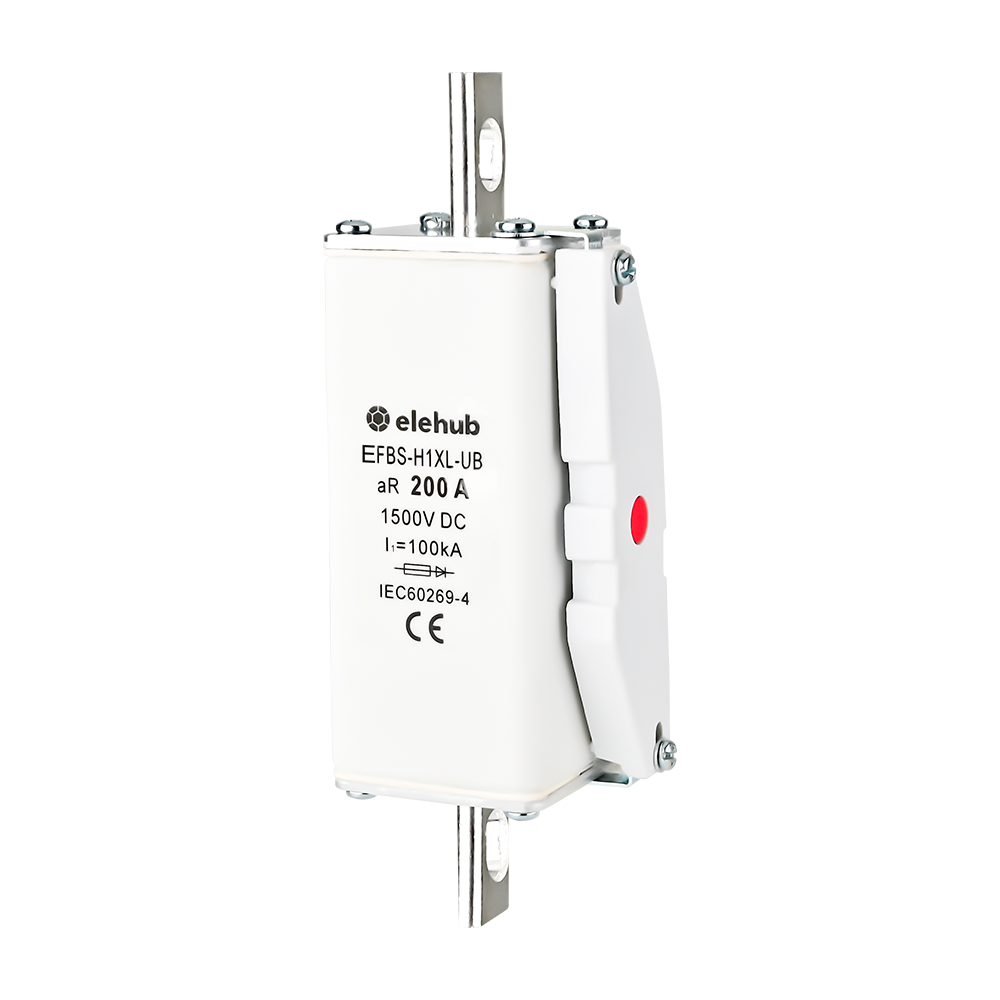
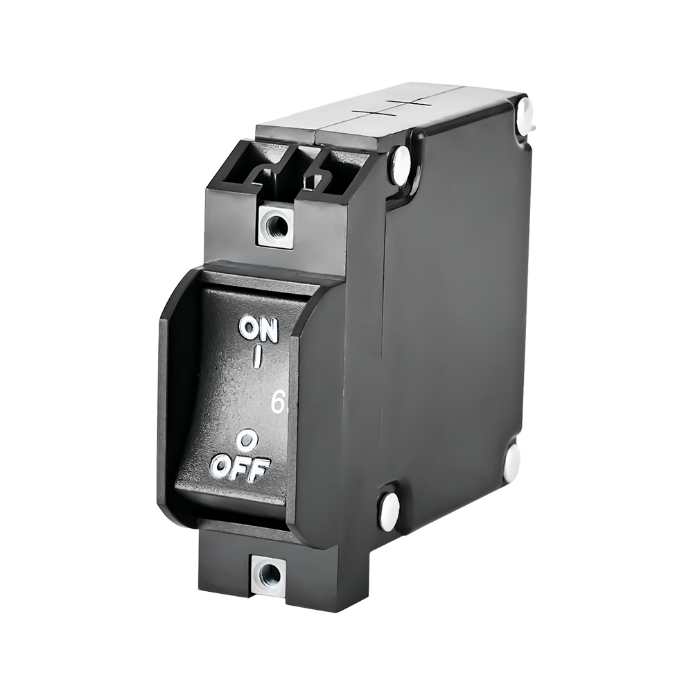
Circuit breakers are a main component of an electrical power system, and one of their most important factors is breaking capacity. Breaking capacity explains how a breaker can safely stop current without damage. If the breaking capacity of circuit breakers is not accurately selected, it can result in damaged devices, cause fires, and even lead to complete system failure.
In this tutorial, we will cover circuit breaker breaking capacity, kA rating, Icu, Ics, and Icm in detail. Understand fault current, selection methods, safety risks, and international standards for proper protection system design.
📌 TL;DR Table: Circuit Breaker Types and Breaking Capacity
| Breaker Type | Breaking Capacity | Main Applications | Key Characteristics |
| MCB | 3–25 kA | Homes, lighting, sockets | Compact, low cost, suitable for low fault levels |
| RCCB | Depends on upstream protection | Earth leakage protection | No overload or short-circuit protection |
| RCBO | 6–16 kA | Residential and light commercial circuits | Combines MCB + RCCB functions |
| MCCB | 10–100 kA | Commercial and industrial feeders | Adjustable trip settings |
| ACB | 25–200 kA | Main LV panels and industrial systems | Very high interruption capability |
| VCB | 16–63 kA | Substations and MV networks | Arc extinguished inside vacuum chamber |
What is the Breaking Capacity of a Circuit Breaker?
Breaking capacity, also known as interrupting capacity in UL standards, refers to the maximum fault current that the breaker can safely interrupt without being damaged or losing its protective function.
It indicates the breaker’s ability to safely stop short-circuit currents under abnormal electrical conditions.
Circuit Breaker kA Rating
The breaking capacity of circuit breaker is expressed in kA (kiloamperes).
For example, a circuit breaker with a 10 kA breaking capacity can safely interrupt a fault current of up to 10,000 amperes.
Typical ranges include:
- 3–10 kA: Residential applications
- 10–50 kA: Commercial and light industrial systems
- 50–100 kA+: Heavy industrial systems
The kA rating is listed on the breaker nameplate and in its technical specifications.

Standard Testing Conditions
To define breaking capacity accurately, engineers must follow standard testing conditions under which the breaker rating is verified. These standard conditions include specific voltage levels, power factors (cos φ), and recovery voltages.
In many circuit breakers, the interrupting capacity increases at lower operating voltages. Therefore, proper analysis of installation conditions is essential.
Important Terms: Icu, Ics, and Icm
Icu, Ics, and Icm are critical short-circuit ratings for electrical circuit breakers:
Icu – Ultimate Short-Circuit Breaking Capacity
Icu is the maximum fault current that a breaker can interrupt without any major failure. It is the highest tested value under standard conditions. It shows the absolute safety limit and is not for normal operation.
After interrupting a fault at Icu level, the breaker may require inspection or replacement before being returned to service.
Ics – Service Short-Circuit Breaking Capacity
Ics is the fault current level where the breaker can interrupt, and in these conditions, the breaker is still usable.
It is defined as a percentage of Icu, such as (25%, 50%, 75%, or 100%).
When the breaker interrupts at Ics, it should continuously function and provide insulation and protection.
Example:
Icu = 10 kA
Ics = 75% of Icu
Ics = 0.75 * 50 = 37.5kA
The breaker has the feature to safely interrupt 37.5 kA many times and still work well, but for 50 kA Icu it needs replacement.
Icm – Making Capacity (Peak Withstand Current)
Icm is the maximum peak asymmetrical current the breaker can withstand when closing onto a short circuit fault. It is not an interruption rating but works with the initial surge (peak current).
Normally, it is 2 to 2.5 times larger than Icu as a result of asymmetrical fault peaks.
🆚 Comparison of Making and Breaking Capacity of Circuit Breaker
| Parameter | Icu | Ics | Icm |
| Full Name | Ultimate Short-Circuit Breaking Capacity | Service Short-Circuit Breaking Capacity | Making Capacity |
| Definition | Maximum fault current a breaker can interrupt under test conditions | Fault current level the breaker can interrupt and remain operational afterward | Maximum peak current the breaker can withstand when closing onto a fault |
| Function | Defines the absolute interruption limit | Defines repeatable and reliable interruption capability | Defines peak withstand capability during switching |
| Current Type | RMS symmetrical fault current | RMS symmetrical fault current | Peak asymmetrical current |
| Operational Requirement | Breaker may require inspection or replacement after interruption | Breaker should continue operating normally | Breaker must withstand mechanical and thermal stress |
| Relation | Base value | Usually 25%, 50%, 75%, or 100% of Icu | Typically 2–2.5 × Icu |
| Main Concern | Safety limit | Reliability and service continuity | Mechanical strength |
| Example | 50 kA | 37.5 kA (75% of 50 kA) | 100–125 kA peak |
How Breaking Capacity Works During Fault Conditions
If a short circuit occurs, the breaker detects, interrupts, and stops the surge of current instantly. It is a high-speed and highly controlled process. Step-by-step operation during a fault is as follows:
1. Fault Current Increases Instantly
When a short circuit occurs, current increases in milliseconds and sometimes 10 to 50 times higher than normal current. This current is known as prospective fault current. Its magnitude is based on the source, transformer rating, and system impedance.
2. Protection Mechanism Detects the Fault
The breaker trip unit detects abnormal current flow and gives a tripping signal. The magnetic trip works instantly when a short circuit occurs and provides high-speed isolation before major damage.
3. Contacts Open Fast
When the breaker trips, the breaker separates contacts mechanically, and separation occurs in milliseconds, but current flow does not stop instantly.
4. Electric Arc Generation
When contacts are separated, current continuously flows through an ionized air path, causing an electric arc. The temperature in these conditions increases to more than 5,000°C. The arc should be controlled and removed quickly.
5. Arc Extinction
In this stage, the importance of breaking capacity is high, and different breakers use different arc-quenching techniques:
- Air (ACB): Arc is stretched and cooled in air chambers
- Oil breakers: Oil vapor extinguishes the arc
- Vacuum (VCB): Arc collapses due to the absence of an ionizable medium
- SF₆ gas breakers: Gas absorbs electrons and cools the arc
6. Current is Interrupted Safely
In AC systems, arc extinction occurs at the natural current zero point.
In DC systems, no natural current zero exists, so forced commutation or electronic/physical arc extinction methods are required.
If the fault current exceeds the breaker’s rated breaking capacity, the breaker may fail, become damaged, or create serious safety hazards such as fire or equipment destruction.
Why Breaking Capacity Matters
Breaker capacity is not only a rating defined in the datasheet; it directly determines whether the protection system operates during fault conditions. When a short circuit occurs, energy increases, and an accurately rated breaker safely controls that energy level.
System Protection Role
A circuit breaker with proper breaking capacity helps the complete electrical system remain safe and stable during fault conditions.
Safe Fault Interruption
The main function is to stop high or dangerous fault currents safely and quickly.
That is helpful for preventing high heat and arcing, controlling damage at the fault point, and allowing the system to shut down in a controlled manner.
Devices Protection
High fault current affects components in a very short time, and accurate breaking capacity is helpful for protection against cable insulation damage, saving transformer windings, and also controlling the burning of sensitive loads and motors.
Electrical System Stability
For complicated systems such as data centers and grids, faults should be isolated locally. This helps in preventing voltage failure, maintaining power for the unaffected part of the circuit, and supporting integration between protection devices.
Controlling Cascading Failures
If the breaker does not interrupt during a fault, the backup protection system stops a larger part of the circuit, and in some conditions, the complete system shuts down.
This is a cascading failure that causes large-scale outages.
Risks of Insufficient Breaking Capacity
Choosing a circuit breaker with improper breaking capacity causes serious faults to the system and also to persons. A sound understanding of these risks is helpful for making decisions and applying accurate safety factors for breaker selection.
Overheating and Thermal Effects
If the fault current is higher than the breaking capacity of the breaker, the instrument does not interrupt the current in its set time. So, arc duration increases and high heat is produced during breaking.
This thermal energy released during extended arcing affects components, insulation, and also affects the breaker structure.
Overheating not only affects the breaker but also other connected devices, the insulation of cables, and panel board components. Serious thermal damage not only increases system downtime but also increases repair costs.
Electrical Hazards
Improper breaking capacity also causes electrical arcs that can lead to dangerous arc flash accidents. Arc flash causes high energy in the form of light, heat, and pressure waves, causing serious injury to persons and also damaging devices.
Failure to extinguish the arc can cause arc flow over different phases or towards ground, and cause system damage and longer outages.
As a result, an electrical fire can spread quickly over cable trays and connected structures.
Devices Failure
Breaker operation beyond its breaking capacity causes mechanical damage such as contact welding, affects functional mechanisms, or causes complete damage to interrupting chambers.
These damages result in the complete stoppage of the protection system, requiring a complete system shutdown and emergency repairs.
Improper functioning of protection devices affects system coordination and selectivity and can cause unwanted tripping and power outages.
Breaking Capacity Ratings by Breaker Type
There are different circuit breaker types used for handling different fault current levels.
Miniature Circuit Breaker (MCB)
Miniature circuit breakers are widely used in residential and small commercial electrical installations. Their typical breaking capacity ranges from 3 kA to 25 kA, with 6 kA and 10 kA being the most common ratings. They are suitable for low fault-level applications.
MCBs are valued for their compact size, low cost, and simple protective function against overloads and short circuits. They are mainly installed in final distribution circuits such as lighting systems, sockets, and small appliances.
However, due to their limited breaking capacity, MCBs are not suitable for industrial systems with high short-circuit currents.

Residual Current Circuit Breaker (RCCB)
RCCB breakers are specifically designed for earth leakage protection. Unlike MCBs or MCCBs, RCCBs do not provide overload or short-circuit protection, so their breaking capacity for fault interruption is not defined independently.
RCCBs detect leakage currents caused by insulation failure or accidental human contact and disconnect the circuit rapidly to prevent electric shock and fire hazards.
They are typically used together with an upstream short-circuit protective device, such as MCBs or MCCBs to achieve complete circuit protection. RCCBs are widely applied in residential, commercial, and industrial installations where personnel safety is a priority.

Source: By Jimbob82 (at en.wikipedia.org) – [1], Public Domain
https://commons.wikimedia.org/w/index.php?curid=2462572
Residual Current Breaker with Overcurrent Protection (RCBO)
RCBO breakers combine the functions of an MCB (overcurrent protection) and an RCCB (earth leakage protection) in a single device.
They are commonly available with three main short-circuit breaking capacity ratings:
| Rating | Typical Applications | Electrical Conditions | Why It Is Used |
| 6 kA | Residential homes, standard domestic consumer units | Higher network impedance due to longer cable runs from utility transformer; lower prospective fault current | Most widely used rating in residential installations; adequate for typical household fault levels and compliant with standard domestic distribution design |
| 10 kA | Commercial buildings, light industrial facilities, residential areas close to distribution transformers | Lower network impedance due to proximity to transformer; higher prospective short-circuit current | Provides enhanced interruption capability and improved safety margin in systems with higher fault levels and denser electrical networks |
| 16 kA | Heavy industry, data centers, hospitals, main switchboards (MDBs) | Very low impedance networks with large transformers and high fault current availability | Required in critical infrastructure and high-energy distribution systems where maximum fault currents must be safely interrupted |
RCBOs provide protection against overloads, short circuits, and earth leakage currents simultaneously. This combination enhances electrical safety by protecting users from electric shock while also safeguarding circuits from overcurrent faults.
RCBOs are commonly installed in circuits where both personal protection and equipment protection are required.

Rail-mounted RCBO
Source: By Dmitry G – Own work, CC BY-SA 3.0, https://commons.wikimedia.org/w/index.php?curid=28907017
Molded Case Circuit Breaker (MCCB)
Molded case circuit breakers are commonly applied in commercial and industrial power systems where higher current ratings and adjustable protection are required. MCCBs generally offer breaking capacities from 10 kA to 100 kA.
Unlike MCBs, MCCBs feature adjustable trip settings that allow better coordination and customization of protection parameters. They are widely used for feeders, motors, and sub-distribution systems.
Their higher interruption capability and flexibility make them ideal for protecting circuits with varying load conditions and larger electrical equipment.

Air Circuit Breaker (ACB)
Air circuit breakers are designed for high-current, low-voltage applications where large fault currents may occur. Their breaking capacity generally ranges from 25 kA to 200 kA, making them suitable for industrial power distribution systems and main low-voltage (LT) panels.
ACBs provide advanced protection functions, including adjustable overload, short-circuit, and ground fault protection. They also support intelligent monitoring and control features for modern power management systems.
Due to their high interruption capability and operational reliability, ACBs are commonly used as main incomers in facilities where fault levels are high and system protection coordination is critical.

Vacuum Circuit Breaker (VCB)
Vacuum circuit breakers are mainly used in medium-voltage power systems such as 11 kV and 33 kV distribution networks.
Common distribution-class VCBs typically range from 16 kA to 63 kA, with standard ratings including: 16 kA, 20 kA, 25 kA, 31.5 kA, 40 kA, 50 kA, and 63 kA. Typical applications include:
| Breaking Capacity Range | Applications |
| 16 kA, 20 kA, 25 kA | Light industrial / small substations |
| 25 kA, 31.5 kA, 40 kA | Standard utility distribution (most common) |
| 40 kA, 50 kA, 63 kA | Large substations, high fault-level networks |
VCBs extinguish electrical arcs inside a vacuum chamber, which provides excellent insulation performance, long service life, and high operational reliability.
They are commonly installed in substations, industrial plants, and medium-voltage distribution systems. Due to their minimal maintenance requirements and strong arc interruption capability, VCBs are widely preferred in modern medium-voltage switchgear systems.

Medium-voltage three-phase vacuum circuit breaker with three vacuum-interrupter housings
Source: By Fesenko kirill – Own work, Public Domain, https://commons.wikimedia.org/w/index.php?curid=7861717
📊 Circuit Breaker Capacity Table: In Summary
| Breaker Type | Breaking Capacity Range | Key Features | Typical Applications |
| MCB | 3 kA – 25 kA | Compact, cost-effective, fixed or limited trip characteristics, fast protection for final circuits | Residential buildings, small commercial loads, lighting and socket circuits (final distribution only) |
| RCCB | Not applicable (no short-circuit rating) | Earth leakage protection only, no overcurrent protection, must be used with MCB/MCCB | Residential and commercial installations |
| RCBO | 6 kA – 16 kA | Combines overcurrent and earth leakage protection in one device, compact safety solution | Residential and light commercial circuits requiring combined protection |
| MCCB | 10 kA – 100 kA | Adjustable thermal-magnetic or electronic trip units, higher capacity, flexible protection settings | Commercial and industrial power distribution, feeders, motor protection, sub-main circuits |
| ACB | 25 kA – 200 kA | High breaking capacity, adjustable protection settings, advanced monitoring and control | Main low-voltage (LV) distribution systems, main incomer panels, industrial power distribution where high fault levels are expected |
| VCB | 16 kA – 63 kA | Arc extinction in vacuum, long electrical life, high reliability, low maintenance | Medium-voltage systems (11 kV, 33 kV), substations, MV distribution networks |
Low vs. High Breaking Capacity Breakers
| Feature | Low Breaking Capacity Breakers | High Breaking Capacity Breakers |
| Typical Range | 3kA to 10kA | 25 kA to 100 kA+ (Up to 200 kA for ACBs) |
| Common Types | MCB, light-duty RCBO | MCCB, ACB, VCB |
| System Level | Final distribution circuits | Main distribution and upstream systems |
| Application Environment | Residential buildings, small offices, light commercial loads | Industrial plants, substations, heavy commercial infrastructure |
| Fault Level Handling | Low prospective short-circuit current | High and severe fault currents |
| Protection Scope | Individual circuits (lighting, sockets, small equipment) | Feeders, main incomers, transformers, large motors |
| Design Focus | Compact size, cost efficiency, simple protection | High safety margin, selectivity, system reliability |
| System Position | Downstream (end-user level) | Upstream (main distribution level) |
| Risk Level If Undersized | Nuisance tripping or device damage | Catastrophic failure if incorrectly selected |
| Cost | Low initial cost | High initial cost |
How to Calculate Circuit Breaker Capacity for Proper Selection
Calculating circuit breaker capacity usually means determining the correct breaking capacity (kA rating) based on the prospective short-circuit current (PSC) at the installation point.
Selection of accurate breaking capacity is not to choose a larger number; it is about the configuration of the breaker with the fault condition of the system. Since oversized or undersized breakers can cause errors, follow these points for selection purposes.
Fault Current Calculation
First, start with the calculation of prospective short-circuit current (PSC) at the installation location, and the main factors included are:
- Transformer rating (kVA)
- Percentage impedance (%Z)
- System voltage (V)
- Cable length and size (affects impedance)
- Source strength (utility or generator)
A simplified estimation formula for transformer-fed systems is:
I_{sc}=\frac{S_{kVA}\times1000}{\sqrt{3}\times V\times Z\%}
\]
Where:
- SkVA = transformer rating
- V = system line voltage
- Z% = transformer impedance percentage
That offers the maximum current the breaker should interrupt.
Use Safety Margin
Do not use a breaker that is equal to the measured fault current. So:
- Add a 20–30% safety margin
- Also consider system expansion, tolerances, and calculation uncertainties
Such as:
- Calculated fault current = 20 kA
- Design requirement ≥ 25 kA breaker
Select Circuit Breaker Breaking Capacity (Icu / Ics)
Now choose breaker rating:
- Icu ≥ calculated fault current × safety margin
- Ics should be ≥ expected operating fault level
Typical practice:
- Residential systems → 6–10 kA
- Commercial systems → 10–25 kA
- Industrial systems → 25–100 kA
Note that fault current is higher closer to the transformer and lower farther from the distribution line.
Check Service Breaking Capacity (Ics)
Do not rely only on Icu.
Check that Ics ≥ expected fault current.
This ensures the breaker can:
- Interrupt faults
- Continue operating afterward
Ics must be about 75%–100% of Icu for important systems.
Verify Making Capacity (Icm)
When switching occurs, the breaker closes onto a fault:
Icm ≥ peak asymmetrical fault current
Normally:
Icm ≈ 2 to 2.5 × Icu
It helps protect the breaker from thermal shocks and mechanical shocks.
Final Selection Rule (Very Important)
A properly selected breaker must satisfy:
✔ Icu ≥ system short-circuit current
✔ Ics ≥ operating requirement
✔ Icm ≥ peak fault current
⚠️ Common Mistakes
- Only using load current (wrong)
- Ignoring cable impedance (overestimates fault current)
- Choosing breaker only based on ampere rating (unsafe)
- Ignoring Ics (affects reliability after fault)
International Standards for Breaking Capacity of Circuit Breakers
Circuit breaker breaking capacity is defined through international standards. These standards help to perform breaker safely in fault conditions and are tested with certain techniques.
IEC Standards
The IEC (International Electrotechnical Commission) standards are the most widely adopted global standards for circuit breakers. They define testing methods, rated breaking capacities, operational performance, and safety requirements for low-voltage and medium-voltage protection devices.

Common IEC standards include:
- IEC 60947-2 → Low-voltage MCCBs and ACBs
- IEC 60898-1 → MCBs for residential applications
- IEC 61008-1 → RCCBs
- IEC 61009-1 → RCBOs
- IEC 62271-100 → Medium-voltage and high-voltage circuit breakers such as VCBs
EN Standards
The EN (European Norm) standards are harmonized European standards largely aligned with IEC requirements. EN standards ensure unified electrical safety and product compliance across European markets.

Examples include:
- EN 60898-1
- EN 60947-2
Manufacturers supplying products to the European Union typically design breakers to comply with both IEC and EN requirements.
UL Standards
In North America, circuit breakers are commonly certified according to UL (Underwriters Laboratories) standards. UL standards focus heavily on electrical safety, fire prevention, and product certification for the United States and Canadian markets.

The most important standard is:
- UL 489 → Molded-case circuit breakers and branch-circuit protection devices
- UL 1077 → Supplementary protectors
UL-certified breakers usually express breaking capacity as AIC (Ampere Interrupting Capacity) rather than Icu / Ics terminology commonly used in IEC systems.
IEEE/ANSI Standards
The IEEE (Institute of Electrical and Electronics Engineers) standards are widely used in North America for power system design, protection coordination, and medium- to high-voltage switchgear applications. IEEE standards work closely with ANSI standards and provide detailed technical guidance for the testing, rating, application, and performance of circuit breakers.

In medium-voltage and high-voltage systems, IEEE standards are especially important for utilities, substations, industrial plants, and power generation facilities.
Common IEEE standards related to circuit breaker breaking capacity include:
- IEEE C37 Series → Standards for power circuit breakers and switchgear
- IEEE C37.04 → Rating structure for AC high-voltage circuit breakers
- IEEE C37.06 → Preferred ratings and related required capabilities
- IEEE C37.09 → Test procedures for AC high-voltage circuit breakers
- IEEE C37.13 → Low-voltage AC power circuit breakers used in enclosures
- IEEE C37.20 Series → Metal-enclosed switchgear standards
Testing of Breaking Capacity Performance
Breaking capacity is not only a design feature; it needs to be checked through different testing methods and maintained over time for reliable working in fault conditions.
Circuit breakers undergo strict testing to confirm they can safely interrupt fault currents under worst-case conditions.
Short-Circuit Testing
It is basic testing and important, since it is performed in high-power laboratories. The breaker faces high fault current that ensures its interrupting current features, arc control and extinction, and structural quality. This test also helps to determine breaker Icu and Ics ratings.
Thermal Endurance Tests
These tests determine the breaker working under continuous load and heating conditions. They check increases in temperature in contacts and conductors.
Helpful for ensuring that insulation is not degrading.
They verify long-term current carrying capability.
Mechanical Endurance Tests
These tests mainly focus on breaker mechanical reliability such as:
- Repeated on/off operation
- Testing latches, moving components, and springs
- Consistent operation during real working life
Arc Extinction Verification
This testing is involved to ensure the breaker controls and extinguishes the arc properly. For this:
- Monitor arc behavior during interruption
- Check arc quenching medium (air, vacuum, SF₆, oil)
- Ensure no restrike
Maintenance Practices
If the breaker rating is accurate, its performance is affected if it is not accurately maintained. Since different factors like heat, wear, and dust affect its features to interrupt faults.
- Inspection of Contacts: Check erosion, pitting, or welding marks on contacts. Since damaged contacts increase resistance, if damaged contacts are found, replace them for accurate working.
- Cleaning Arc Chutes: Arc chutes guide and cool the arc; dust reduces arc control. So clean properly to ensure proper arc extinction.
- Checking Trip Mechanisms: Ensure accurate working of thermal or electric trip units and provide fast and reliable tripping when a fault occurs. So, if needed, perform calibration.
- Thermal Scanning: Check hotspots and abnormal heating to find loose connections or internal faults. This helps manage unexpected failures.
Industrial Trends in Circuit Breaker Technology
Circuit breaker technology is growing rapidly with increasing complexity, digitalization, and energy-based electrical systems. There is a need for reliable operation, compactness, intelligence, and adaptability for new energy systems. Some new circuit breaker technologies are:
Smart Circuit Breakers
Conventional breakers trip when a fault occurs, but advanced breakers are intelligent devices that:
- Come with IoT-based monitoring systems for the detection of remote current, voltage, and breaker conditions
- Provide real-time fault diagnostics helpful for finding reasons for instant tripping
- Offer data logging compatible with performance analysis and reporting
These features make breakers work as both protection devices and monitoring tools.
Digital Protection Integration
Circuit breakers are not fully digital but support digital power systems. They come with:
- Integration with SCADA and energy management systems
- Remote control operations
- Recording and fault history tracking
- Predictive maintenance compared to reactive repairs
These features increase system uptime and avoid sudden failures.
Higher Efficiency Materials
High-efficiency materials enhance breaking working performance.
Good arc-quenching materials prevent wear during faults and increase insulation for better safety margins.
They also help reduce contact erosion and increase working life.
Compact High-Capacity Designs
New breakers are small and high power, as high breaking capacity exists in compact dimensions.
Compact design for panels and switchgear and modular structure for flexible installations.
It is most important for electric vehicle designs, data centers, and compact industrial panels.
Renewable Energy Support
The use of renewable energy is also changing breaker demand, requiring designs for wind power, EV charging, and solar PV systems.
It has features for managing bidirectional power flow (generation + load).
It also enhances DC breaking features for battery and solar systems.
Conclusion
Breaking capacity is a fundamental safety factor that helps to determine whether an electrical system can handle and interrupt fault conditions. The idea of Icu, Ics, and Icm is important since Icu explains the maximum interrupt limit, Ics defines reliable and repeatable operations, and Icm manages peak current during switching.
In residential projects, the use of MCB, and for larger systems based on MCCB or ACBs, choosing the correct breaking capacity has effects on system protection, safety devices, and operational continuity.
In this fast-growing power system, like EV charging, battery storage, and renewable energy systems, reliable switching and protection are important. High-quality components of ELEHUB, such as advanced DC contactors and reversing contactors, offer safe and effective control for DC circuits in demanding conditions.
Therefore, a properly designed protection system requires correctly rated circuit breakers (kA rating) combined with suitable switching components to ensure reliable performance and electrical safety.
FAQs
What does the ka rating on a circuit breaker mean?
The kA rating on a circuit breaker indicates its breaking capacity, meaning the maximum short-circuit current it can safely interrupt without damage under standardized test conditions.
Does a higher kA rating make a circuit breaker safer?
Not necessarily. A higher kA rating means it can withstand larger fault currents, but safety depends on correct system matching, not oversizing alone.
Can a circuit breaker still work after interrupting a fault at Icu level?
It may still function, but it is not guaranteed. After Icu-level interruption, the breaker often requires inspection or replacement before reuse.
What happens if the fault current is lower than the breaker’s breaking capacity?
The breaker will operate normally. A higher breaking capacity simply means extra safety margin, not reduced performance.
Is breaking capacity related to the rated current (In) of a breaker?
No. Rated current (In) refers to normal operating load, while breaking capacity (kA) refers to short-circuit fault interruption capability.
Why do two breakers with the same amp rating have different kA ratings?
Because breaking capacity depends on internal arc-quenching design, contact materials, and mechanical structure—not just current rating.
Does temperature affect the breaking capacity of circuit breakers?
Indirectly, yes. High ambient temperatures can reduce overall performance margins, but breaking capacity is defined under standardized test conditions.
Can breaking capacity degrade over time?
Yes. Mechanical wear, contact erosion, and aging of arc chambers can reduce real-world interruption performance over long-term use.
How is breaking capacity verified in practice?
It is confirmed through standardized short-circuit tests in laboratories under IEC/UL testing conditions, not during normal field operation.
How to increase capacity of circuit breaker?
You cannot increase a circuit breaker’s breaking capacity after manufacturing. To handle higher fault levels, you must replace it with a higher kA-rated breaker or reduce system’s short-circuit current.