There is a possibility that a battery pack may pass its voltage tests but still not start an inverter. The cells are healthy. The cables look fine. However, somewhere between the start command and normal operation, the electrical system stops the sequence.
Often, that interruption deserves attention before anyone orders replacement parts. The startup process has its own unique electrical requirements, and a precharge circuit is responsible for managing a transient event that cannot be described by a stable current rating.
This approach is widely used in electric vehicles (EVs), battery energy storage systems (BESS), EV charging equipment, inverters, and industrial DC power systems.
Knowing that event gives designers, equipment buyers, and service teams a better basis for decisions.
What Is a Battery Precharge Circuit?
A battery precharge circuit is a controlled path that limits inrush current while downstream DC-link capacitors charge. It typically uses a precharge resistor and contactor. Once the DC-bus voltage reaches the defined threshold, the main contactor closes and establishes the normal low-resistance power path.
A conventional passive arrangement consists of:
Battery → Precharge Contactor → Precharge Resistor → DC Bus → DC-Link Capacitor
The main power path runs in parallel:
Battery → Main Contactor → DC Bus → Inverter
When the DC-link capacitor is initially discharged, the voltage difference between the battery and capacitor can cause a large current surge if the main contactor closes immediately.
E.g., dividing a 400 V difference by 0.05 Ω gives 8,000 A. That resistance-only estimate is not a predicted waveform. Battery impedance, cable inductance, and capacitor characteristics affect the actual transient. But it explains why ordinary operating current tells only part of the story.
The term precharging describes this startup stage. Note that you may also encounter “prcharge circuit” or “precharging circuit” in drawings and equipment manuals.
Despite “precharge battery” and “pre charge battery,” the circuit discussed here prepares the load’s capacitors. It does not replenish the battery’s state of charge. This comes in handy when comparing battery charging equipment with components for battery connection control.

Precharge circuit with exponential voltage growth curve
Source: https://commons.wikimedia.org/w/index.php?curid=92514939
Why Does a Precharge Circuit Matter?
An uncharged capacitor initially presents a large voltage difference to the battery. With little resistance in the connecting path, current can surge enough to damage connectors, open fuses, or pit and weld contactor contacts.

Source: https://commons.wikimedia.org/w/index.php?curid=92514952
The problem is not limited to a single high-current event. Repeated uncontrolled inrush can place additional electrical and thermal stress on the contactor, wiring, fuses, busbars, and DC-link capacitors. In systems that start and stop frequently, these repeated transients can gradually affect component reliability.
A precharge circuit reduces this stress by allowing the DC-link capacitors to charge through a controlled resistance before the main contactor closes. The main contactor then carries the normal operating current rather than the initial capacitor-charging surge. This makes the startup sequence more predictable and helps protect the components in the high-voltage DC path.
In a similar context, Texas Instruments explains that pre-charge circuits help limit inrush current and reduce stress on high-voltage components. Its application brief also shows how a controlled pre-charge sequence can charge the DC-link capacitor before the main contactor closes, helping prevent contact damage and unwanted arcing.
How Does a Precharge Circuit Work?
The controller moves through defined states. In the context of a common arrangement with positive and negative main contactors, the sequence is just like the following:
- Check System Readiness: Confirm valid measurements, acceptable interlock status, and the expected initial bus condition. Keep downstream power conversion disabled.
- Establish the Return Path: The negative main contactor closes first in a typical arrangement, while the positive main contactor remains open.
- Energize the Resistor Branch: Close the precharge contactor. Note that when there is a decrease in the charging current, the DC-link capacitor voltage increases.
- Verify Precharge Completion: Compare the measured DC bus voltage with the battery voltage. Moreover, check the permitted current and timing conditions.
- Transfer to Normal Operation: Close and verify the positive main contactor, release the resistor branch according to the approved sequence, and permit the load to operate.

Battery Precharge Circuit Diagram
Once the capacitor voltage rises sufficiently close to the battery voltage, the main contactor closes and provides a low-resistance path around the precharge branch. The precharge circuit therefore does not normally carry the system’s full operating current. Its primary job is to manage the short startup period while the DC-link capacitor is charging.
A battery management system (BMS) may supervise the process. A BMS precharge circuit needs feedback from the load side as well as the battery. Remember, a timer alone cannot establish whether or not charging actually occurred.
Also distinguish a command from a result. Even when the coil is powered, this does not indicate that its power contacts are closed. The precharge circuit in BMS applications should evaluate contactor feedback or suitable voltage measurements before advancing.
Main Components in Battery Precharge Circuit
A precharge circuit consists of more than a resistor and contactor. Depending on the system architecture, it may also include voltage and current sensing, control electronics, and circuit protection.
| Component | Engineering Purpose |
|---|---|
| Battery | Defines the system voltage range and available fault energy. |
| Precharge Contactor | Connects the battery to the DC link through the precharge resistor during startup. |
| Precharge Resistor | Limits inrush current and absorbs the capacitor charging energy. |
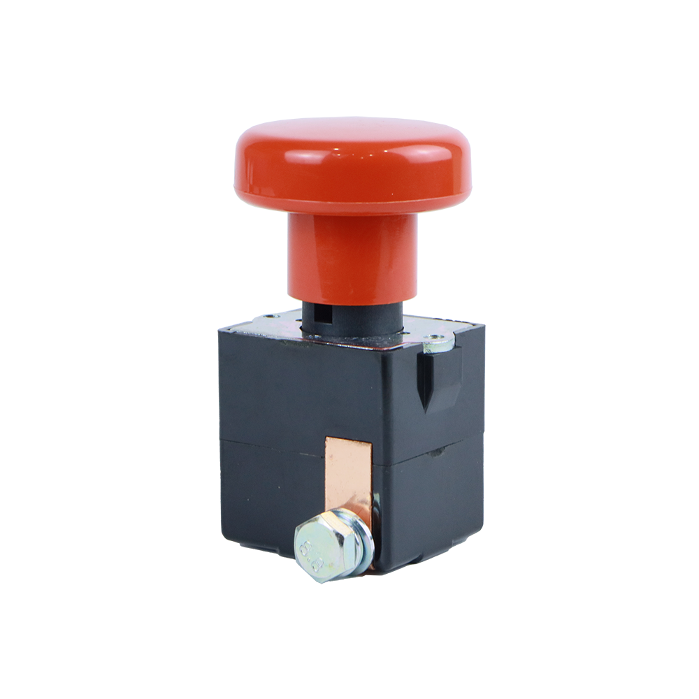
| Main DC Contactor | Establishes the main battery-to-load current path after precharge is complete. |
| DC-Link Capacitor | Provides local energy storage at the converter input. |
| Switching Devices | Establish or isolate the required current paths. |
| Voltage Sensor | Measures battery and DC-link voltages to verify precharge progress. |
| Current Sensor or DC Shunt | Monitors branch or pack current for control and protection. |
| Controller / BMS | Manages the precharge sequence and determines when the main contactor can close. |
| Circuit Protection | Protects the circuit against short circuits and excessive fault current. |
ELEHUB’s DC shunts support current measurement. In contrast to the charging resistor, the extremely low resistance of a shunt serves a very different function.

DC shunt circuit diagram for current measurement
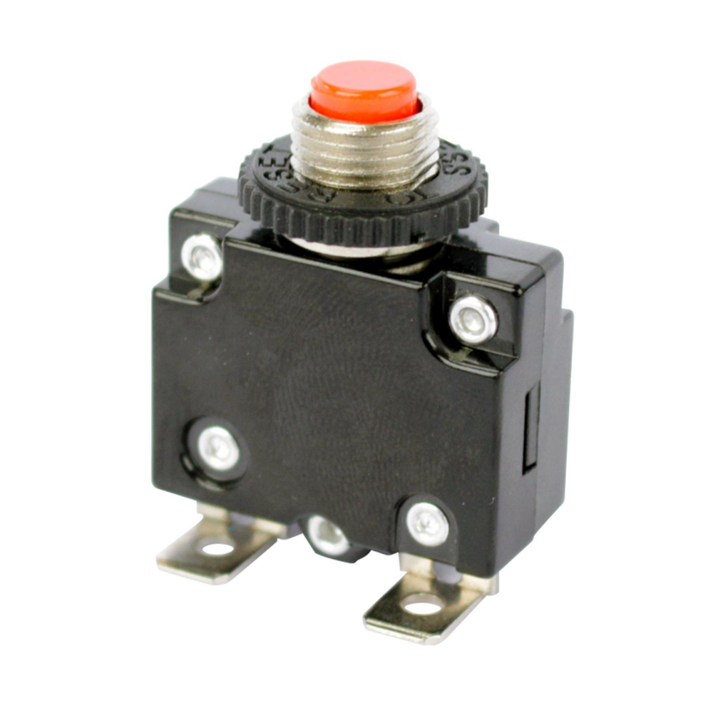
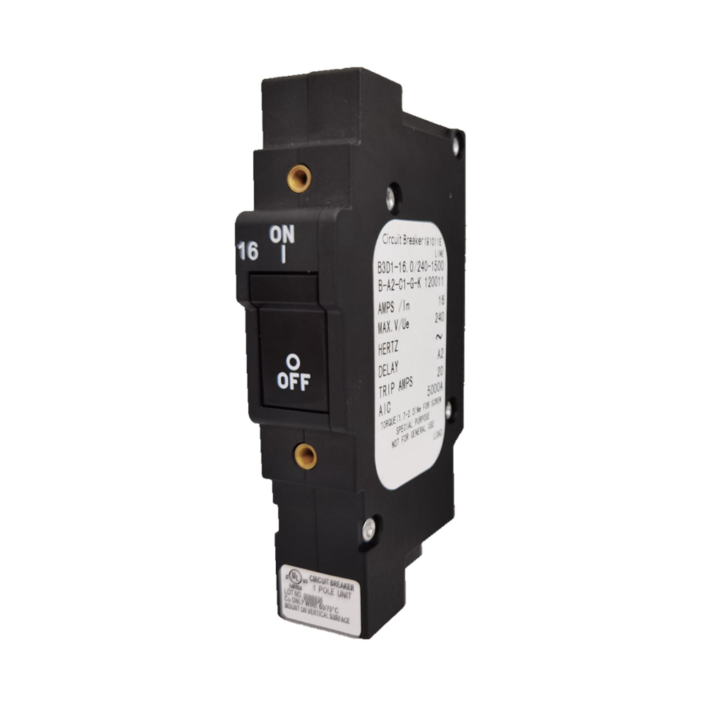
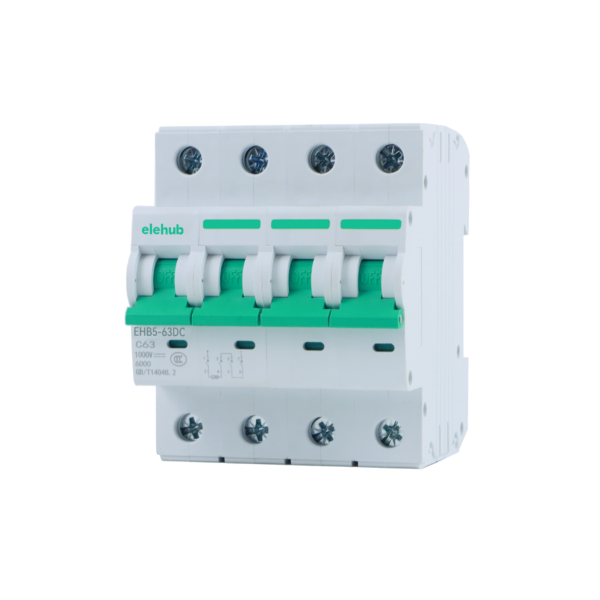
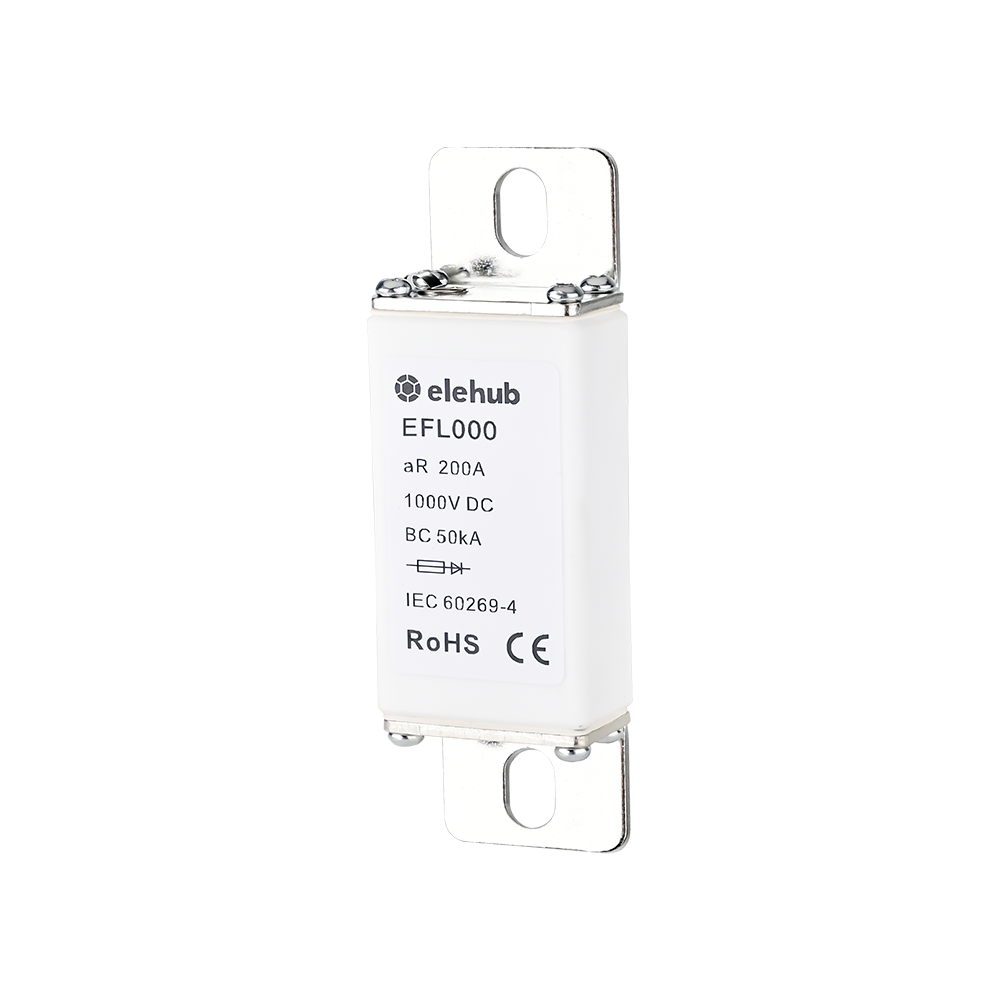
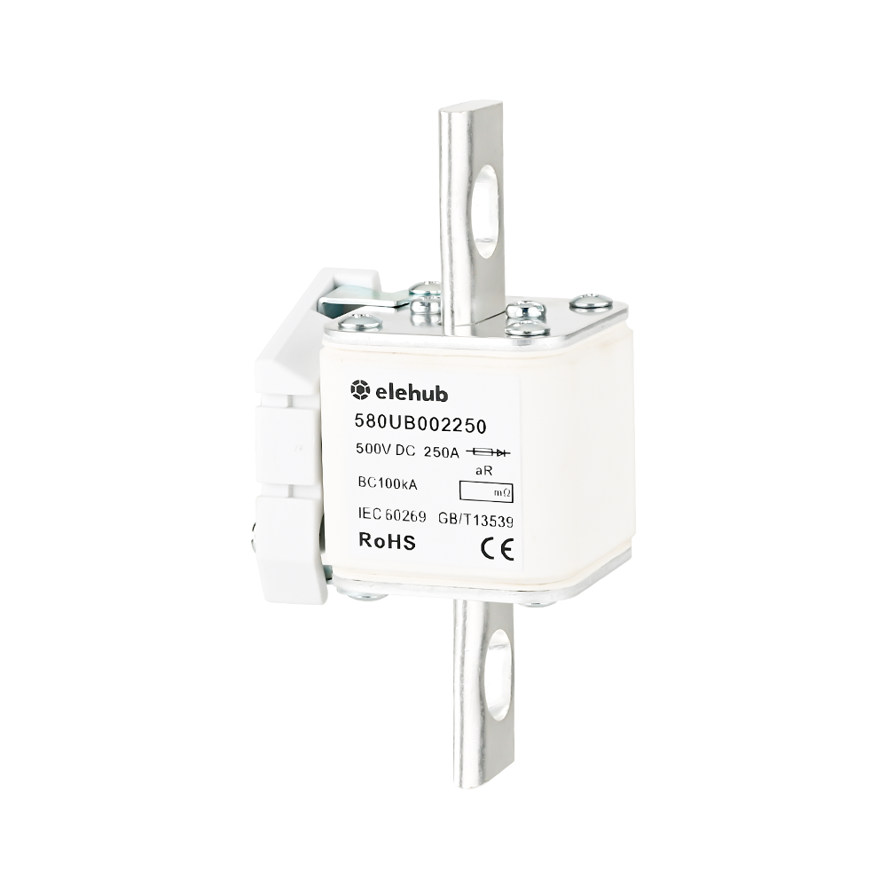
A protection coordination study should be used to choose DC fuses and circuit breakers, depending on whether or not the architecture requires them. Voltage ratings, interrupting capacities, and operating curves of these components must be compatible with the circuit.
Precharge Contactor vs. Main Contactor
The two devices face different duties even when their housings look similar.
| Feature | Precharge Contactor | Main DC Contactor |
|---|---|---|
| Primary Function | Controls the precharge path and limits capacitor charging current. | Controls the main battery-to-load power path. |
| Typical Current | Lower, short-duration charging current. | Higher, sustained operating current. |
| Series Resistor | Yes, connected in series with the precharge path. | No, provides the low-resistance main path. |
| Operating Period | Mainly during startup and interrupted precharge. | Normal operation, shutdown, and specified fault conditions. |
| Current Assessment | Pulse magnitude, duration, and repetition. | Continuous current and overload profile. |
| Opening Duty | Normal release and interrupted startup. | Normal shutdown and specified emergency interruption. |
| Thermal Assessment | Repeated startup events and pulse energy. | Extended operation at enclosure temperature. |
| Design Priority | Voltage rating, switching capability, pulse duty, and thermal limits. | Voltage rating, continuous current, switching capability, and fault duty. |
A lower current rating does not automatically mean a lower voltage requirement. Both contactors can experience the battery’s full voltage across open contacts.
Likewise, carrying current and breaking current are separate specifications. A contactor that carries a stated amperage may not interrupt that amperage at every DC voltage. Check the manufacturer’s switching conditions, including current direction and circuit inductance. There is no way to determine whether a precharge relay circuit is suitable based just on the relay label.
How to Calculate a Precharge Resistor
Begin with maximum battery voltage, total connected capacitance, initial capacitor voltage, allowable startup current, and the required completion time.
Calculate Resistance and Charging Time
For an ideal precharge resistor circuit with negligible load current:
\( I_0 = \frac{V_b – V_0}{R}, \quad \tau = RC \)
Where:
- I0 = initial precharge current
- Vb = battery voltage
- V0 = initial capacitor voltage
- R = total series resistance
- C = total capacitance
Normally, the selected precharge resistor dominates the resistance.
For a discharged capacitor:
\( V_C(t)=V_b\left(1-e^{-t/(RC)}\right) \)
Rearranging for a target fraction
\[ f=\frac{V_C}{V_b} \]
gives:
\[ t=-RC\ln(1-f) \]
OpenStax’s RC circuit treatment establishes these charging relationships. They give approximately 63.2% at one time constant, 95.0% at three, and 99.3% at five. Make a note that these percentages describe the model and not mandatory completion thresholds.
Consider a 400 V system with 2,000 µF of capacitance and a nominal 5 A initial current target:
| Calculation | Result |
|---|---|
| Minimum nominal resistance: 400 ÷ 5 | 80 Ω |
| Time constant: 80 × 0.002 | 0.16 s |
| Time to 95% | About 0.48 s |
| Time to 99% | About 0.74 s |
If 5A is an absolute limit, allow for resistor tolerance and maximum actual voltage. If you choose precisely 80 Ω, there will be no tolerance margin.
Check that the timing requirement is achievable with that current limit. Reaching 99% within 0.5 s would require about 54.3 Ω or less with the same capacitance. That conflicts with the 80 Ω minimum. The specification must change, or the charging architecture must change. A larger wattage resistor cannot resolve incompatible electrical targets. This feasibility check belongs before detailed component selection, when revising the requirements is less costly.
Check Pulse Energy and Temperature
For charging from zero through an ideal resistor, heating equals the final stored capacitor energy.
\( E_R = \frac{1}{2}CV_b^2, \quad P_0 = I_0^2R = \frac{(V_b – V_0)^2}{R} \)
The example produces 160 J of resistor heating and 2,000 W of initial instantaneous power, calculated from assumptions. For nonzero initial voltage, complete equalization dissipates:
\( E_R = \frac{1}{2}C(V_b – V_0)^2 \)
These results show why a catalog wattage alone cannot qualify a precharge resistor. Check its pulse energy curve, working voltage, mounting requirements, ambient temperature, and cooling interval. There is the possibility for several precharge resistors to share stress, provided that their voltage and energy distribution are taken into consideration.
Increasing resistance cuts peak current but extends charging time. It does not cut the ideal energy dissipated during complete equalization. Repeated starts accumulate heat. A shorted load can maintain power throughout the timeout. Precharge circuit design must evaluate both conditions.
How to Choose a Precharge Contactor
Specify the electrical duty before choosing a model. Check:
- DC Voltage Capability: Use maximum charged pack voltage and applicable transient needs.
- Pulse Performance: Verify closing current, pulse duration, and permissible repetition.
- Fault Interruption: Establish what happens if startup must stop while current still flows.
- Coil Compatibility: Match supply voltage, driver capacity, suppression, and pickup conditions.
- Installation: Review insulation, terminals, mount orientation, vibration, and temperature limits.
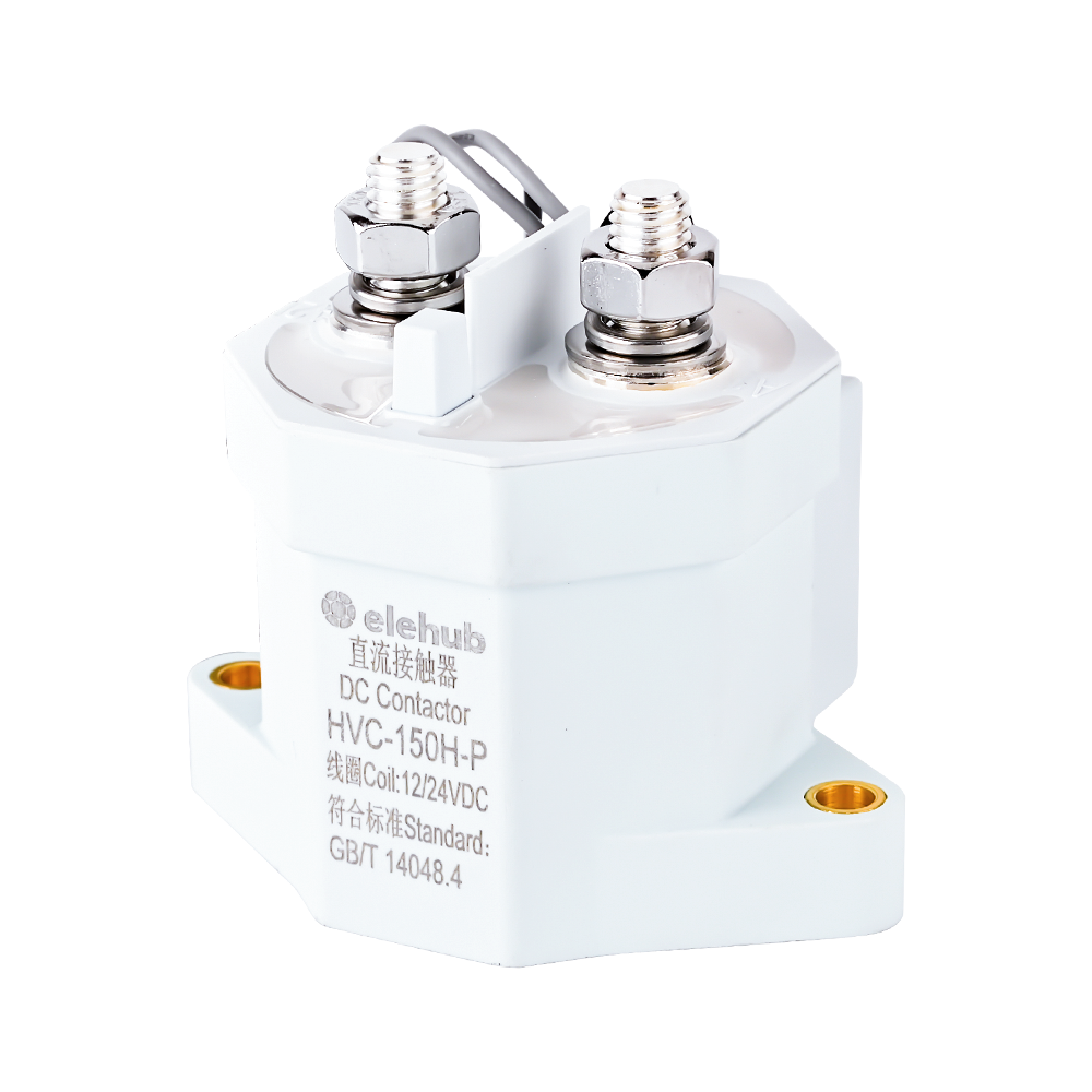
Once the voltage, pulse current, switching duty, and coil requirements are defined, compare contactors against the complete application. For example, ELEHUB’s HPC20 and HPC40 precharge contactors offer 450 VDC-rated options with 12 or 24 VDC coils. Both use normally open, single-pole contacts with QC or PCB coil terminals.
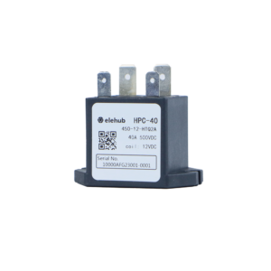
These are starting points for selection, and these should not be considered as pulse performance guarantees.
Ask for electrical endurance under the proposed duty, too. Mechanical life without an electrical load cannot predict contact life during repeated charged switching. Coil suppression also affects release time, which the controller must accommodate when it commands an interruption.
Confirm the exact variant and approved datasheet with ELEHUB. Neither listed 450 VDC rating establishes correctness for an 800 V battery system.
Precharge Circuit Design Considerations
Good precharge circuit design accounts for component variation and controller behavior.
Battery Voltage
The maximum battery voltage determines the required contactor voltage, insulation, and switching ratings. Current capacity alone is not sufficient for high-voltage applications.
DC-Link Capacitance
Higher capacitance requires more charging energy and time. Consider capacitance, resistor tolerance, downstream load, charging time, and pulse-energy requirements together.
Precharge Completion Condition
Define a voltage threshold for closing the main contactor based on its closing capability and the remaining voltage difference. For example, a 400 V bus at 95% charge still has a 20 V difference. Account for sensor accuracy, filtering, contactor delay, and loop impedance.
Require the voltage to remain within the acceptance range for a defined period, and set a maximum precharge time. On failure, isolate the precharge branch and block main contactor closure. If bus voltage is received through communication, stale data must never qualify precharge completion.
Resistor Pulse-Energy Rating
Continuous wattage does not determine pulse capability. Consider energy per cycle, pulse duration, startup frequency, ambient temperature, and cooling conditions.
Contactor Switching Capability
Select contactors based on actual DC operating conditions. Check voltage, continuous current, make/break current, short-circuit duty, coil requirements, and electrical endurance.
Control, Sensing, and Fault Handling
The controller or BMS should verify battery voltage, DC-bus voltage, current, and contactor status. Sensor faults, communication loss, excessive current, or timeout should prevent main contactor closure.
Passive vs. Active Precharge
Passive designs use resistors to limit capacitor charging current, while active designs regulate charging electronically. Active approaches can reduce charging losses or provide more controlled current, but they add switching devices, control circuitry, and thermal considerations.
For either approach, define the topology clearly and evaluate charging voltage, capacitance, charging time, efficiency, thermal load, and fault behavior.

Source: Texas Instruments
Layout and Thermal Considerations
Keep sensing wires away from switching noise and maintain required creepage and clearance. Position heat-generating components away from sensitive wiring and evaluate thermal behavior during repeated startups.
For NTC-based precharge circuits, also consider hot restarts. Resistance decreases as the thermistor heats up, so a short power interruption may leave it too warm to provide the intended current limiting. Its cold resistance alone does not represent every startup condition.
Precharge Circuit in EVs
An EV precharge circuit must account for every load connected when an electric vehicle starts up. A traction inverter, compressor drive, and auxiliary converter may contribute input capacitance even while their power stages are not actively operating.
The precharge circuit in electric vehicle platforms therefore needs a load inventory. Automotive DC link capacitance ranges from several hundred to thousands of microfarads. Using only the traction inverter’s value can underestimate the connected total.
A precharge circuit for motor controller integration should also coordinate readiness messages and torque inhibition. Charging the DC link does not authorize the motor to produce torque.
For an FSAE precharge circuit, the event’s current rulebook governs the acceptance criteria. Document the thermal limits and shutdown behavior of any precharge circuit FSAE inspectors will review. Obtain the applicable documents through Formula SAE’s official resources. Rules from another competition or an older season may differ.

Design and thermal considerations of EV precharge circuits
Precharge Circuit in Battery Energy Storage Systems
When it comes to a battery energy storage system, the situation is altered by the electrical state of the shared bus. It is likely that the power conversion system has an input that has been discharged, or that another battery rack may have energized the bus.
- For the first condition, the inverter precharge circuit prepares the converter’s DC link.
- For the second condition, the control system must assess the voltage difference and possible current direction before having to connect another rack.
A capacitor charging resistor is not a general solution for paralleling batteries at different voltages. Their sustained energy exchange demands its own connection strategy.
Place the battery precharge circuit where it can manage the capacitance that is assigned to it. Apart from that, document which controller owns each connection. Include maintenance isolation, black start behavior, and recovery after an interrupted grid event. Otherwise, two controllers can issue individually reasonable commands that conflict at the shared bus.
And when it comes to larger installations, engineering review should incorporate cabinet temperature and access for replacement, as well as the electrical calculations.
Storage capacity in kilowatt-hours does not determine resistor value. Two installations storing the same energy may have different converter capacitances, rack arrangements, and connection schedules. Size the startup branch from those actual conditions.

Architecture of a Battery Energy Storage System
How to Test a Precharge Circuit
Testing requires personnel competent in the equipment’s voltage class. HSE advises isolating and securing high-voltage systems, proving them dead, and addressing stored energy before work. Follow the manufacturer’s procedure and use appropriately rated instruments.
1. Inspect the Isolated Circuit
Compare the wiring with the approved diagram. Check the precharge resistor, contactors, terminals, coil connections, and sensing polarity. Measure resistance only with the circuit isolated.
2. Check Battery and DC-Bus Voltage
Confirm the battery voltage is within the expected range. During precharge, verify that the DC-bus voltage rises toward the battery voltage as expected.
3. Check Precharge Current
Measure the precharge current and compare it with the calculated value. The current should decrease as the DC-link capacitor charges.
4. Verify Contactor Operation
Confirm that the precharge and main contactors receive the correct control signals and operate in the intended sequence. Use contactor feedback or voltage measurements to verify actual contact closure.
5. Record the Startup Process
Capture battery voltage, DC-bus voltage, precharge current, contactor commands, and contactor status on the same time base. Use appropriately rated differential or isolated measurement equipment.
Compare the measured voltage rise with the calculated charging curve and record the voltage difference and current transient before main contactor closure.
6. Check Control and Fault Logic
Review precharge timing, voltage thresholds, current limits, contactor feedback, BMS logic, and timeout behavior. Verify that sensor or communication faults prevent unintended main contactor closure.
7. Test and Record Relevant Conditions
Repeat testing within specified temperature, supply, and duty limits. Retain test traces together with hardware and firmware revisions for future troubleshooting.
⚠️ Safety note: Precharge circuits in EV, BESS, and industrial DC systems can involve hazardous voltage and stored energy. Only personnel qualified for the equipment and voltage class should test, using the manufacturer’s procedures and appropriately rated measurement equipment.
Common Precharge Circuit Problems and Troubleshooting
A fault identifies an unsuccessful sequence. It doesn’t automatically identify a failed resistor. Begin with the observed waveform and the controller’s stored fault data.
| Observation | Possible Cause | Diagnostic Direction |
|---|---|---|
| Bus voltage never rises | Open resistor, missing return path, inactive relay | Check branch continuity and actual switching state. |
| Voltage rises but stalls | Premature load operation, leakage, excessive resistance | Compare charging current with downstream demand. |
| Bus energizes before the command | Welded contact, backfeed, retained charge | Identify the voltage source before restarting. |
| Resistor overheats | Repeated attempts, prolonged loading, failed bypass | Review event history and branch current duration. |
| Contactors chatter | Coil supply sag, unsuitable suppression, unstable command | Capture coil voltage and driver signals. |
You have to preserve diagnostic records before resetting faults. Repeatedly retrying an unexplained failure can destroy evidence as well as increase component stress.
For a component review, contact ELEHUB along with maximum pack voltage, connected capacitance, target startup time, measured current profile, and expected operating conditions. Those inputs support a specific selection discussion for your precharge circuit.
Conclusion
A battery precharge circuit controls inrush current while DC-link capacitors charge, helping protect contactors and other high-voltage components from excessive electrical stress.
A reliable design requires the right combination of precharge resistor, contactor, sensing, protection, and control logic. Before selecting components, consider battery voltage, capacitance, startup time, current, pulse energy, and switching conditions.
For EV, BESS, and other high-voltage DC applications, ELEHUB offers DC contactors and related protection components for precharge and battery connection systems.
FAQs
Why is precharge needed in a battery system?
It prevents excessive capacitor charging current that can damage components or cause main contactor contacts to weld.
What is a precharge resistor?
A precharge resistor temporarily limits current between the battery and DC-link capacitors during startup.
What does a precharge contactor do?
The precharge contactor connects the battery to the DC bus through the precharge resistor during the initial charging stage.
What happens if a precharge circuit fails?
The DC bus may not reach its expected voltage, the resistor may overheat, or the main contactor may be prevented from closing.
How long should precharge take?
It depends on system capacitance, resistance, allowable current, and the required bus-voltage threshold. The target should be defined during system design.
Can a precharge resistor be used to connect two batteries?
Not necessarily. Connecting batteries at different voltages is a different problem from charging a DC-link capacitor and requires a suitable battery connection strategy.
Does a precharge contactor need a high DC voltage rating?
Yes. Its voltage rating must cover the maximum system voltage and the actual switching conditions, including the required opening and fault-interruption duty.
How do you know when precharge is complete?
The control system typically compares the DC-bus voltage with the battery voltage and confirms that the voltage difference is within the defined acceptance range.
Can a precharge circuit prevent contactor welding?
It can significantly reduce the capacitor inrush current that contributes to contact stress, but correct contactor selection and system protection are still required.